As cloud-based solutions continue to proliferate, it’s clear that the virtualized video revolution has already begun.
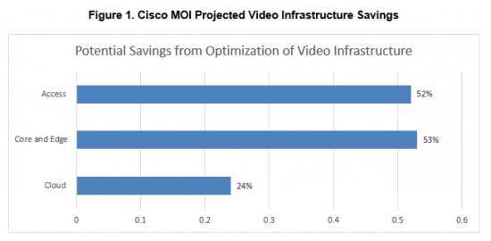
How much of your video infrastructure still relies on dedicated appliances? Today, a growing number of pay TV providers are taking a different approach. By virtualizing key functions – transcoding, content management, content delivery network (CDN), and others – they can cut their video delivery costs by up to 33 percent, according to Cisco forecasts.
Can you really cut a third of your costs through virtualization? Absolutely. Here’s how.
1. Scale with demand
For the first source of savings, consider how video networks are designed today. Not only are the custom appliances used for each video processing function expensive individually; you have to deploy enough of them to handle peak usage. That means, for example, building out a dedicated video on demand (VoD) infrastructure to handle peak Friday night viewing times, even if most of those resources sit idle the rest of the week.
When you virtualize the VoD platform and associated video functions, your need for custom hardware disappears. You can use a shared pool of compute and storage resources and dynamically reallocate resources according to demand. Need more transcoding? Spin up more resources from the shared pool. Want to burst VoD resources on Friday nights, and then reallocate them to other applications the rest of the week? No problem. In effect, you’re replacing expensive and under-utilized custom appliances with a smaller hardware footprint that does the same things more efficiently.
2. Lower operating costs
Operational expenses play a big role in that 33 percent saving. After all, when you’re using custom appliances for diverse video processing functions, you need a data center to house them. Multiple dedicated infrastructures built for peak transcoding, content management systems (CMS), and other functions take up a lot of square footage. They require a lot of cooling. They consume an enormous amount of power.
By virtualizing those functions and delivering them from a smaller footprint, you eliminate a huge amount of redundancy and unused capacity. Your video cloud can now accommodate the same scale from a facility a fraction of the size, which costs much less to maintain.
3. Optimize architecture
Virtualization also allows for a more distributed video architecture, which lowers the overall cost of your network. When CDN, transcoding, and more are virtualized functions running on standard x86 platforms, you can easily distribute them out into the network. So you’re reducing core and edge bandwidth even as you’re lowering costs in your video data center/cloud. You can also push gateway, caching and video optimization functions closer to subscribers, reducing traffic in access networks.
Add it all up, and it equals major capital and operational savings, lower long-term access investments and lower total cost of ownership (TCO) [see Figure 1].
We’re just getting started
It’s worth remembering that the 33 percent savings projection only addresses the first stages of the virtualized video revolution. Within the next few years, you can also expect substantially lower software licensing costs as video providers shift from proprietary virtualization frameworks to open-source solutions, like OpenStack.
Many pay TV providers are also now looking at hosted cloud solutions – whether private or public – for their virtualized resources. These offer even more flexibility to scale with demand, and often better economics than building out capacity in house. Even more importantly, they reduce time-to-market because you can deploy, test and scale new video services much faster.
Learn more
Plug in your own parameters in our Monetization and Optimization Index and create a customized model of what virtualization can mean for your video infrastructure.
For more examples of how other providers are using virtualization to lower costs and optimize video infrastructures, visit www.cisco.com/go/v2p.
At the recently concluded OpenStack summit in Austin, I was impressed by the amount of interest shown by attendees on containers. Almost all of the container related sessions were packed as customers are now realizing its advantages. By containerizing applications, you are able to virtualize the host operating system. What this means is that you now create isolated environments within the host OS for each container, such as the file system, network stack and process space that prevents containers from seeing each other. Besides, the containers are also light-weight and portable not only across the OS distributions but also across clouds. These features enable developers to quickly build, deploy, port and scale apps in a manner that was not possible before with apps running in a virtual machine environment.
At the summit, I had the opportunity to present to a fairly large group of audience on one of my passionate projects that immensely helped our team. A recording of my presentation can be found here- my session . The project was to stand up an automated deployment of Kubernetes in our OpenStack Kilo environment. In this blog post, I will describe our approach and also provide an overview of the code repo available on github for anyone to use. Hopefully, you could leverage some of these to build an automated deployment of your own Kubernetes cluster. Do keep in mind that the software has been tested in a development environment only and for any production deployment ensure that you conduct the necessary due diligence as always.
The first question to answer is the why and what of kubernetes and ansible. Kubernetes (k8s) is an API driven platform for orchestrating and managing docker containers. Besides basic orchestration, it also has control processes that continuously drive the state of the system towards the user specified desired state. When using this platform you have the ability to group your application containers together into a composite unit called pod. A pod is a grouping of containers that share networking and storage. When you create docker containers, by default, each container gets its own network namespace i.e. its own TCP/IP stack. Kubernetes combines the network space of all its pod containers by using the –net=”<container-name>|<container-id>” setting in docker. This setting enables one container to reuse another container’s network stack. K8s accomplishes this by creating a pod level holding container with its own network stack and all of the pod containers are configured to use reuse the holding container’s network space.
At the pod level, kubernetes provides a variety of services such as scheduling, replication, self-healing, monitoring, naming/discovery, identity, authorization etc. Kubernetes also has a pluggable model that enables developers to write their own modules and build services atop this platform. As of this writing, it is one of the most advanced open-source platforms available to orchestrate and manage docker containers.
We chose Ansible for automation as is one of the most popular, intuitive and easy to use automation platforms today. It is agent-less and uses ssh to login to systems in the infrastructure and enforces policies that you have described in a file called a playbook. The policies are modeled as a list of tasks in yaml format. In the world without automation, these could be thought of as the manual tasks that an IT admin would have to execute to deploy the infrastructure software.
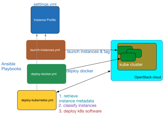
This post describes how to setup a working kubernetes cluster on OpenStack virtual machines. A K8s cluster has a master node, which runs the API server and a set of worker nodes that run the pod containers. The setup uses Ansible (>2.0), Ubuntu and Neutron networking. It has been tested using the OpenStack kilo release. Ansible deploys the k8s software components, launches VMs, classifies VMs into master and worker nodes and deploys kubernetes manifests. We use neutron to provide networking to both the OpenStack VMs and k8s pod containers. All VMs in the test environment run the ubuntu 14.04 server OS.
The below diagram shows the various software components in play and how they interact to automate the cluster. I will use this diagram as a reference to illustrate the automation process and it should all make sense as you read through this post.
Kubernetes Cluster Automation
Setup
This setup assumes that you have an OpenStack cloud running core services such as Nova, Neutron, Glance and Keystone. You will also need ansible version >2.x, on a machine that has the credentials and network connectivity to ssh into the compute nodes and VMs. This ansible node should also be able to access the OpenStack APIs. I have ansible installed on my macbook using the commands:
sudo easy_install pip
sudo pip install ansible
After you have installed ansible, verify its version using the command: “ansible –version”. It should output a 2.x. release.
Kubernetes Cluster Deployment
The automated cluster deployment is controlled by three ansible playbooks. You can pull the playbooks, templates and code from my repo here: cluster repo . The three playbooks are
deploy-docker.yml — deploys docker on all of the cluster instances
deploy-kubernetes.yml — deploys kubernetes control and worker software components and brings up the cluster
All playbooks get their input variables from a file named settings.yml, which will be referred to as the settings file. The nodes dictionary in the settings file specifies the names of the nodes in the cluster along with their metadata a.k.a. tags, that are injected into the nodes at launch time. These tags are used by a cloud inventory script [ inventory.py ] to classify the nodes as master and worker during subsequent playbooks runs. For instance, the node whose tag ansible_host_groups equals k8s_master will be classified as the master node and the nodes whose tag value equals k8s_worker will be classified as workers. The settings file also contains a dictionary named os_cloud_profile, which provides ansible with the nova virtual machine launch settings. To launch the instances, run the playbook as below:
ansible-playbook -i hosts launch-instances.yml.
If everything goes well, you will see that all the nova instances are created without any errors in your OpenStack cloud. These instances will provide the underlying infrastructure to run the k8s cluster. After spawning the instances, you can run the remaining playbooks to deploy docker and kubernetes. During the playbook run, use the inventory script named ‘inventory.py’ to classify nodes so the control and worker components are deployed to the correct VMs.
The control plane for the k8s cluster which includes the API server, scheduler, etcd database and kube controller manager is deployed using a master manifest file. This file can be found in the templates folder and is named master-manifest.j2 . The version of the k8s control plane software is determined from the settings file. The playbook named deploy-kubernetes.yml first downloads and deploys the kubelet and kube-proxy binaries and starts these two services on all the nodes. Then the master-manifest template file is deployed to a config directory named /etc/kubernetes/manifests on the master node. This directory is watched by the kubelet daemon process and it starts all the docker containers that provide control plane services. When you use the docker ps command, you should see the kube-apiserver, kube-controller-manager, etcd and kube-scheduler processes running in their own containers in the master node.
The API server is configured to use HTTPS to serve the API. The certificates needed for SSL are generated by running the script make-ca-cert.sh as one of the playbook tasks. This script generates the below certificates in the certificate directory on each node. It is generated on each node because the docker daemon is also configured to use the same server certificate for TLS. The cert directory value is configurable in the settings file.
ca.pem – Self signed CA certificate
server.crt / server.key – Signed kube API server certificate and its key file. This cert is also used by the docker daemon process to secure client access.
cert.pem / key.pem – Signed client certificate and its key file. Used by both the kubectl and docker clients.
On the client machine, you can find these certs in the certs folder within the repo. Docker environment files are created in the client machine for each node using the convention <nodename>.env. You can source this environment variables and run the docker client against its docker host. For example to run docker commands on the master node named master1, first do a “source master1.env” and then run the commands. Also, for the kubectl client a config file is created with the necessary credentials and cluster master IP address. The config file could be found in $HOME/.kube/config. This will enable you to run the kubectl commands from your terminal window against the cluster.
Using OpenStack neutron for Kubernetes Networking
In this post, I will describe how to use the OpenStack neutron service for networking the k8s pods. This is similar to the setup used in GCE. There are other options such as flannel that uses UDP encapsulation to create an overlay network for routing pod traffic over existing tenant neutron networks. Using neutron for pod networking removes this overlay-over-overlay network architecture for containers.
It is important to note that in k8s each pod i.e. a group of containers, has an IP address. This is different from the networking model in docker in which each container has its own host private IP address. In order for k8s networking to work, the pod ip addresses must be made routable without NAT. This means two things:
a) When a pod container communicates with other containers in other pods, the traffic must be routed directly without NAT
b) When a pod container communicates with the IP address of the VM, the traffic must be routed directly without NAT
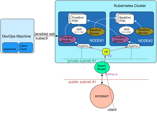
In order to accomplish this, as a first step, the default docker bridge named docker0 in each node is replaced with a linux bridge named cbr0. An IP block is allocated for pod networking across all nodes say a /16. This block is subnetted and a node-to-pod cidr mapping is created in the settings file. In the above digram, I have allocated 10.1.0.0/16 for pod networking and created a mapping as below:
node1 : 10.1.1.1/24
node2: 10.1.2.1/24
nodeN: 10.1.n.1/24
A script named create-bridge.sh [create-bridge.sh] creates cbr0 and configures it with the IP address of the pod subnet using the mapping defined in the settings file.
The second step is to configure the tenant router to route traffic to the pod subnet. For example in the above diagram, the tenant router must be configured to route the traffic to the pod subnet 10.1.1.0/24 to the node#1’s ethernet address on the private-subnet#1. Similarly a route must be added with a destination pointing to each node in the cluster on the tenant router to route traffic destined to the pod network. This is accomplished using the script add_neutron_routes.py .
The third step is to add an ip tables rule to masquerade traffic destined from the pod subnet to the Internet for outbound connectivity. This is because the neutron tenant router does not know that it needs to SNAT the traffic from the pod subnet.
The last step is to enable ip forwarding on the linux kernel of each node to route packets to the bridged container network. All of these tasks are performed by the playbook deploy-kubernetes.yml .
The end result of running this playbook is that neutron networking is now programmed to route traffic between the pods and to the Internet.
Note: By default, as an anti-spoofing security measure, neutron installs iptables firewall rules on the hypervisor to lock-down traffic originating from and destined to a virtual machine’s port. So when you route traffic destined to the pod network to the virtual machine’s port, it is filtered by the hypervisor firewall. Fortunately, there is a neutron extension named AllowedAddressPairs , which is available as of the Havana release that allows additional networks such as the pod subnets to pass though the hypervisor firewall.
Exposing Pod Services
For all practical purposes, each pod must be front-ended by a service abstraction. The service provides a stable IP address using which you can connect to the application running in a pod container. This is because the pods could be scheduled on any node and can get any IP address from the allocated node_pod_cidr range. Also, as you scale-out/scale-back these pods to accommodate varying traffic loads or even when failed pods are re-created by the platform, their IP addresses will change. The service abstraction ensures that the ip address of the pods remain fixed from the a client’s perspective. It is important to note that the CIDR for the service, also known as cluster_cidr, only lives locally in each node and does not need to be routed by the neutron tenant router. Traffic hitting this service IP is distributed by k8s to the backend pod using a proxy function (kube-proxy) implemented in each node typically using iptables.
This stable service ip can be exposed to the outside using the NodePort capability of kubernetes. What nodeport does is that it uses the IP addresses of the worker node and a high tcp port say 31000, to expose the service ip address and port to the external world. So if you allocate a floating-ip to the node, the application will serve traffic on that ip and its node-port. If you use a neutron load balancer, add the worker nodes as members and program the vip to distribute traffic to the nodePort. This approach is illustrated in the above diagram.
Service Discovery
Service discovery is fully automated using a DNS cluster add-on service. This is deployed using a skydns-manifest and skydns-service . Every service defined in the cluster is assigned a DNS name automatically by k8s. So an application running in a pod can lookup the cluster dns server to resolve the service name and location. The cluster DNS service supports both A and SRV record lookups.
Conclusion
In conclusion, I hope this blog post has shed some light on how to standup a Kubernetes cluster within OpenStack using Ansible. Feel free to send me your comments and suggestions. You can reach me at najoy@cisco.com.
It was in mid-March, I posted a blog about the new level of simplicity Cisco Nexus Fabric Manager (NFM) brings when configuring your fabric underlay and VXLAN overlay. Essentially…a point-and-click approach without requiring a single CLI command or any knowledge of IP protocols.
Since the release of Nexus Fabric Manager in early April, it’s gotten a high level of interest (lots of POCs) and traction, exceeding expectations from customers or all sizes and verticals. In my book…exceeding traction milestones is always a good sign that customers are seeing true value in the solution.
Proud Product Team
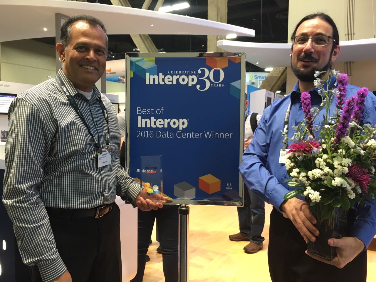
Yesterday, we got yet another industry validation! Judges consisting of the most influential IT practitioners, analysts and professionals who base their decisions on the technologies that “have the most significant technical impact on their segment and are helping to move business technology forward”, awarded the Cisco Nexus Fabric Manager the Best of Interop 2016 Data Center award.
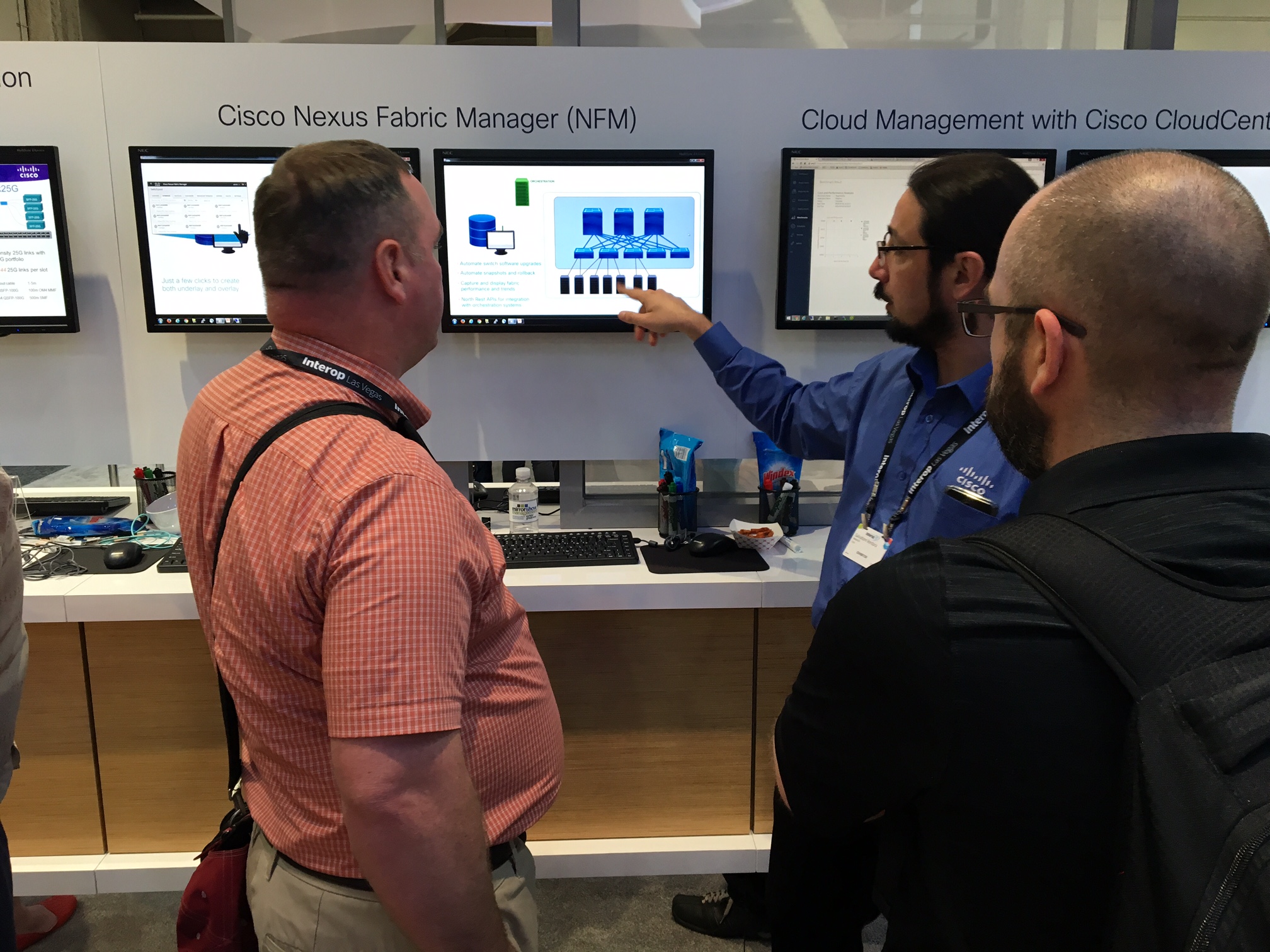
At the Nexus Fabric Manager demo booth at Interop…there was a common theme to comments made by many attendees.
“This is great. I need to get a copy into the lab for my team to test asap.”
“Very cool. But I feel kind of “dirty” using this instead of doing dozens of cli commands”
“Need to test drive this as soon as I get home…this could really simplify my life”
“One of the coolest and simplest GUI tools for a Cisco product”
And my Favorite
“I don’t need to learn BGP-EVPN VXLAN CLI commands?”
Salvatore Giving a Demo
At the end of the day….It’s always easy to win awards when you have a great product that helps customer solve their problems!
I invite you to read my March blog on NFM and also visit the NFM website for more information on how NFM can help you simplify your job/life…or for a quick overview, watch this short NFM overview video to get a good idea what NFM is all about.
We went to Austin for BBQ, and an OpenStack Summit broke out…
…OK, maybe that’s not entirely true, but the BBQ was good.
When we started this journey less than 5 weeks ago in preparation for the Austin OpenStack Summit, we’d already collectively had many OpenStack deployments under our belts, both manually deployed and through the use of automation, for example through the use of automation tools like Ansible. We went from days and weeks to deploy, down to hours. We experienced a lot of pain each time, even as we’d done our Nth deployment. But we somehow felt that, even with automation, it was not good enough. Some capabilities were still missing from the final product.
With CI/CD so pervasive now, coupled with DevOps, we thought that there must be a better, faster way to commoditize the spin up of an OpenStack cloud. In other words, could we make it available to the masses. To plot our course, we needed a vision of what a good deployment might look like.
Our Vision
So what was our vision when we talk about the OpenStack control plane? Ideally, it would have some of the following characteristics:
Easily Deployed: With minimal steps, I have a functional OpenStack environment, spending fewer man-hours, and requiring minimal expertise, especially around configuration and troubleshooting.
Consistent & Repeatable: Any deployment should be repeatable and easily replicated across organizations with consistent outcomes. We want to spend less time troubleshooting when we have consistent outcomes.
Quickly Operationalized: In many OpenStack deployments, we need to overlay an Operations stack to effectively monitor the OpenStack deployments. This takes a specific set of engineering skills. Ideally, I would like have an operational, fully functioning stack in 5-10 minutes, including monitoring its behaviors and the ability for straightforward, in-service upgrades.
Customizations: Should be able to quickly and easily drop in value-added features and services.
Scalability: Ideally, this would be mostly “hands-off”, and should expand to a maximum scale to meet demand, but then retract to a minimum “guaranteed” scale when demand subsides.
Self-Healing: Any solution should also self-heal upon failure. In other words, let’s put our primary focus on maximizing availability and secondarily addressing the cause of failure.
Improved Service Level Agreements: With more uptime, and confirmation that services are performing at the level that is expected, we expect improved SLAs.
The focus of this blog post is to give attention to addressing a solution that is Easily Deployed, Quickly Operationalized, be Consistent and Repeatable across DevOps, and finally, Self-Healed, with our primary focus on availability.
The Pain
Pain is a great motivator, and as previously mentioned, we experienced a lot of it during our deployments of OpenStack. Here are three areas where we’ve experienced some pain, which were key motivators driving our thoughts.
Deployment
Everybody wants it fast (or yesterday)!! When we talk about “fast”, it’s usually synonymous with automation. And furthermore, most people would agree that automation is table stakes in DevOps. Some automation tools are now available using Ansible, Chef, Puppet, etc. These have emerged to aid and speed deployment, some of which a few OpenStack projects utilize (e.g., Kolla). But these have the appearance of being adjunct to the core of OpenStack, and are still time consuming to setup.
Despite improvements in OpenStack documentation, they are still targeted to more of a generalized deployment approach, with indications of what knobs to tweak for added flexibility. And while OpenStack is quite flexible, it is this flexibility that organizations struggle to overcome when adapting to their deployment architecture. Enterprises are left with a “do it yourself” approach or utilizing one of many vendor turn-key solutions.
Inconsistencies in build and deployment environments
What worked last week no longer works this week!!!! Differing dependencies between development, staging and production environments can lead to breakage at any point along the way (e.g., packages, libraries, operating systems distros, kernel version). Some of this may be attributable to complicated organizational processes, which tend to have many moving parts, with many points of failure and opportunities for miscommunication.
Operationalization
First off, we need to engineer what our system should be capable of handling. That is, what is the appropriate scale, or how big should we make it to meet our anticipated demand? This capacity planning and scale testing adds significant, up-front man-hours, which can delay time-to-market. And yet, even with such planning, systems still tend to be over-provisioned because no one really knows what demand will be. Furthermore, when additional capacity is needed, expanding a system may result in more capacity than needed. We then must “stitch in” that added capacity into our system. Of course, the other side of this coin is that added capacity is not always removed when it’s no longer needed, leaving excess capacity stranded. So by having elasticity, we could spend less time with up-front engineering, moving quickly to service deployment, allowing an auto-scaling system to handle elasticity around our pre-determined policies.
When we talk about operationalization, traditional monitoring tools are not enough anymore; they are more reactive than proactive. We need more advanced tools to collect additional metrics (e.g., U-S-E), metrics that trigger failovers or adapt scale based on demands. Such metrics can also provide teams with solid feedback on where adjustments may be needed. Of course, it is desirable that some of the metrics collected are tied to business outcomes. For example, latency tied to user experience, because after all, isn’t user experience what it’s all about anyway? But every coin has two sides. More advanced tooling requires specialized engineering skills to standup and monitor.
As we’ve stated in our vision, our primary focus is service availability first, and failure cause is secondary. We also lack built-in service healing without utilizing overlay automation. Again, self-healing should be the desired end-game, with our attention placed on service availability and, where finding the cause of failures, should be secondary.
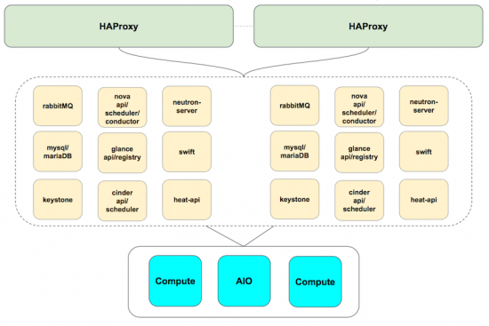
Traditional OpenStack Control Plane Design
So what makes up an HA control plane, and where do some of our pain points manifest? We know that the goals of an HA control plane design are to eliminate single points of failure. We have multiple compute instances, of course. We lay in our networking and controllers, replicate as needed, and glue it altogether using tools like keepalived and load-balancers. Finally, we throw in some fixed scaling decisions, and, viola!!, we have our HA stack.
In its traditional form, this type of design has some pain points. Generally, when a service is created, expanded, or contracted, the load-balancing function must be updated to reflect the changes in the service. This can be a tedious, error-prone, manual process, or may require an overlay of orchestration to complete. We’d prefer if these load-balancing updates are handled behind the scenes, without our intervention.
Control plane components are HA as we note, were the redundant services are distributed across various controller instances. This works well under optimal conditions, such as, where demand is at or near “engineered” levels or under single fault conditions. But when a fault occurs, HA may be lost on multiple services because those replicated services tend to be bunched together. With demand at or near engineered levels, this may be tolerable. But under higher load, perhaps not so much. Moreover, we may invest several man-hours trying to determine where the failure cause lies. We’d like to have a self-healing control plane, and know with confidence that a service would function with maximum availability.
When we build out a traditional control plane, we tend to take our best-guess estimate, or even utilize some empirical data, to predict anticipated demand. While imperfect, it can lead to over or under-engineered systems. These issues may manifest as poor user experience (e.g., due to high latencies) or underutilized capacity. Over-utilization results in either a rebuild to expand capacity or requires additional nodes. This may then lead to idle / unused capacity during low demand periods. It becomes challenging to find the right balance, and operationally it becomes onerous to manage. It became clear that we’d much rather prefer if our system can scale up or down to meet demand, operating within a minimum or maximum range, with workloads placed when and where needed.
Enter Kubernetes: A light in a sea of darkness
When considering the key aspects of our Vision mentioned previously, we think about many of Kubernetes’ attributes, and the attributes of containers in general, and how these can accommodate many of our needs. Let’s quickly review some of those.
Kubernetes’ advantages
Declarative – Allows your applications to be deployed quickly and predictably. Kubernetes works to monitor the current state of services and synchronizes it with the desired state as defined by you. This means that if an application container temporarily goes down, and you have declared that you need three copies of that application, it is the responsibility of Kubernetes to start up another container.
Scale – applications are scaled on demand instead of requiring resources to be allocated statically. The current version of Kubernetes can scale up to 1,000 nodes and 30,000 containers per cluster.
Easy to Build and Update – You can build a fully functional, self-healing control plane in as little as 5 minutes. You can seamlessly roll out new features to existing deployments without the need for downtime.
Efficient – Use only the resources you need, avoiding over provisioning and increasing your average server utilization rate.
Why Kubernetes has value in an OpenStack control plane
Some of the nicest features about Kubernetes, and why it gets our attention, is its self-healing attributes; namely, auto-restart, auto-scale, auto-replication. Those are features that are needed now, not tomorrow.
It’s consistent with your build and your resources. You pragmatically and efficiently use only the resources you need…on demand.
It has built-in API health checks (specifically, application- or service-centric health checking) as well as the afore-mentioned self-healing services help lead to greater uptime of services. And more up-time is always a good thing, right?
Redesigning our OpenStack control plane
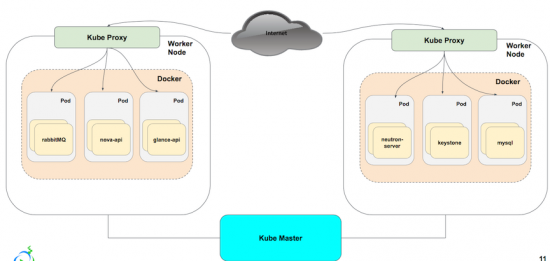
Reviewing our previously discussed HA control plane architecture, and then updating it with the proposed architecture, we replace the HAProxy instances with kube-proxy. Each service is built out separately, and managed and monitored via Kubernetes. We achieve failover by having multiple copies of each service, that we scale up or down based off of need. The load balancing that we found to be tedious to update with HAProxy, is updated in unison, without the need to reconfigure manually or through a separate layer of automation.
The architecture looks similar to the tradition HA control plane from an exposed service perspective, but in the next section you’ll see how we’ve built, scaled, and monitored our control plane within Kubernetes.
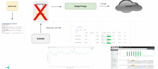
Self Healed OpenStack Control Plane
First, we build each OpenStack service (in this case glance-api) from a corresponding Dockerfile, matching our defined standard (version, packages, volumes, and config)
Containers are built as replicated services, grouped together as pods, and exposed via kube-proxy as an OpenStack service port.
Health check probes, which are native to the build process and managed by the kubelet, are added to each pod configuration to perform pre-build readiness checks as well as the check the health of the pod post-build.
In the instance of a pod failure (and provided you’ve declared more than one replica in your build), then a copy is rebuilt, making the service ‘self heal’.
And then we leverage Kubernetes built-in monitoring to detect service disruption/repair as well as customizing our resource utilization.
Why We Selected Kubernetes?
Provisioning and Orchestration
What we like about Kubernetes is that it’s a complete, automated container platform. With it, we can have a fully functional, self-healed control plane in about than 5 mins, thus spending less time on the installation/configuration and more time customizing it to fit our needs. It’s also easier to provision and orchestrate new or existing applications, as pods can start in seconds versus the minutes it takes VMs to startup. Finally, it allows us to eliminate the need to worry about over/under provisioning, reducing the time needed for additional capacity planning.
CI/CD Consistency
First off, it’s easy to deploy and maintain applications. Since Kubernetes leverages Docker as the build and deployment artifact, we gain a portable and sharable package in which a company can deploy their software to almost any infrastructure stack. Anyone who can build a Dockerfile can build a replicated service application in Kubernetes.
We also like that Kubernetes provides fully-integrated deployment options like rolling updates (for version or security purposes as an example), greenfield/brownfield deployments, and A/B testing. We found upgrading to no longer be a disruptive procedure, but a productive one.
Scaling
Benefit of the Kube-Service is its ability to maintain connectivity to the the underlying service aggregation even when it is rescheduled to a different node after failing and/or if the Pod’s IP address changes. A key benefit for us is that it wasn’t a necessary to spend additional time to reconfigure a load balancer due to change….Kubernetes does it for you.
We also like that there’s significant cost reduction by increasing your average server utilization rate and therefore reducing your server footprint. Many environments run their VM’s with a low utilization rate (sometimes as low as 10%) while applications in a Kubernetes cluster can see a much higher utilization rate (often as high as 70%).
Self-healing
Kubernetes has built in self-healing mechanisms, such as auto-restarting, re-scheduling, and replicating containers. As a user, you just define the state and Kubernetes ensures that the state is met at all times on the cluster. We’ve all had issues troubleshooting OpenStack services, whether it’s in the pre-build architecture or post build service failure. With the ability to maintain service uptime, you replace the “what happened?” with “well, it self-corrected.”
I’d like to reiterate the point that **maximizing service availability should always take priority** to finding the cause of failure. Not to ignore the cause, but up-time is king to maintaining any guarantees on your SLA.
Closing Thoughts
OpenStack deployment can be easy and fast
With manual installation/configurations of the ancient age, we talked about days of work to bring up an OpenStack cluster with tons of “Layer 8 errors” and months chaos. With the advent of automation tools such as Ansible, we brought it down to hours; however, that was still not good enough. As we demonstrated at the Austin OpenStack Summit, it is possible to have a fully-automated approach to having a functional, self-healed OpenStack control plane in 5 mins. For our friends in Service team and Q/A team, we would love to hand it over to you so you can spend less time on installation/configuration, and MORE time to make your customer happy, or develop/execute automated test suite to ensure the code is always in deployable state.
CI/CD is quite feasible
Throughout the cycle of Continuous Integration, Continuous Delivery, Continuous Deployment, we anticipate small batch sizes of work flowing through Dev, to Q/A, to Operation teams. The original thinking is to dramatically increase the productivity by creating an environment on demand, limiting WIF, and build a system which is safe to change. However, in reality, quite often that is not the case. It causes more delay due to inconsistency between Development environment (for unit and functional testing), and Staging environment (to test business logic, find design issues and corner cases in the scale testing), and Production environment, which is the counter to the ultimate goals for any business. Given the nature of container to packaging your apps and its dependencies such as library and binaries, we can create a virtual isolation on top of your physical servers to avoid the conflicts; Don’t forget that Kubernetes provides lifecycle management, so creating an env on demand is quite feasible. When your Developers needs an env, we can bring it up in secs; When she doesn’t need it, we can remove it within secs. It’s never been so easy before.
Operations will become more challenging…but still achievable
For our friends from the Operation teams, please don’t feel that you are being left out. With all of this good news for the Dev, Q/A teams, we have a bit of bad news for you. When you get paged 2 in the morning, you may already have felt the pain of OpenStack control plane. Now with at least three replicas, the complexity level is at least multiplied by 3. To make the matters worse, the container names can be changed due to self-healing and the number of containers can be quite dynamic triggered by autoscaling; Considering the 10+ deployments every day, the complexity level will be exponential. However, we firmly believe a solid operational solution is still achievable, and perhaps, we can make this the talk of a future post.
It is all about improving efficiency
For the Decision Makers, we can summarize this article in one word: EFFICIENCY. It is all about improving the efficiency (sales and sales velocity), isn’t it? What has been discussed is a new way of applying a technology, developed outside of OpenStack community, onto the OpenStack cloud itself. The business value is quite obvious. It drives down the cost and increases the usability of your OpenStack cloud by a significant factor. If you are willing to shift cost-performance curve even further, then join us in Barcelona and we will show you more.
Cisco just received wonderful news from SAP: Customers love us!
OK, we already knew that – not because we are all above-average looking (although we are) or because we’re hounded at the grocery story by Cisco groupies (it could happen) – but because we see it consistently in every study of Cisco’s SAP customers.
IDC found on average, SAP users who implement on Cisco UCS realize a whopping 528% ROI and an incredibly rapid 9 month payback!
So although this is welcome news, it isn’t a surprise to learn that Cisco was selected as aFinalist for SAP’s 2016 Pinnacle Award in the Customer Choice: Build category.
We’re especially honored to receive this award because it’s dependent upon unsolicited customer nominations; meaning the most important people in the world vote on this, Real Life Customers.
Cisco UCS Integrated Infrastructure is the secret handshake that makes it happen. Our SAP customers benefit from fully integrated compute, storage, and network solutions that are tested and certified, and further supported by our unique Cisco Validated Designs (CVDs).
SAP’s customer award for Build, i.e., deployment, is further evidence that our SAP solutions really do what they are designed to do:
Shorten implementation time,
Improve manageability,
Enhance security,
Drive superior ROI, and most importantly,
Help our customers become more competitive and improve their bottom line.
A sincere thank-you to all our customers who showed us the Love with your votes. For anybody interested in learning more, please talk to a Cisco representative or visit our SAP website to find out if “Superior ROI” is right for you.
Historians often point to The Renaissance many centuries ago as humankind’s most creatively prolific period. Indeed, timeless discoveries and masterpieces in art, literature and science burst forth from geniuses such as Leonardo de Vinci, Michelangelo, and Galileo.
I spend a lot of my spare time studying about social and cultural change, and I respectfully disagree with such historians. I passionately believe that future historians will look back and agree that today – right now – stands as humankind’s most creatively prolific time.
Guest Blog Submitted by Jeff Meek, Manager, Product Marketing, SP
Almost $1 trillion will be divided among mobile operators in the next few years. Are you fully prepared to take your share?
Growing numbers of mobile users and a fast-changing competitive environment: that’s the opportunity, and the challenge, for mobile operators today. With voice traffic declining and revenue being lost to over-the-top providers and Wi-Fi access networks, it’s up to you to bring to market compelling mobile services to capture new revenue – or risk watching your market share disappear.
Let’s look at the latest numbers and forecasts. According to the Cisco Visual Networking Index (VNI) Global Mobile Data Traffic Forecast, by 2020 there will be 5.5 billion mobile users around the world. That’s up from 4.8 billion in 2015. There will also be 11.6 billion connected mobile devices by 2020 – more than two per user. In 2015, mobile offload exceeded cellular traffic for the first time. Fifty-one percent of total mobile data traffic was offloaded through Wi-Fi or femtocell.
Cisco applied data from the Cisco VNI, as well as research by ABI Research, IDC, AMI-Partners, Gartner, and Frost & Sullivan, to create a tool that models the impact of these rapidly developing changes. The Cisco Monetization and Optimization Index (MOI) features revenue forecasts for five different service categories, and lets you explore opportunities to monetize specific service offerings.
A world connected
Overall, Cisco forecasts there will be 50 billion connections to the “internet of everything” by 2019, bringing $892 billion in new revenue from mobile, media and entertainment, cloud infrastructure and cloud services.
For the mobile market, the Cisco MOI features three mobile services from which you can expect to reap major revenue in the next few years. Together, these services will generate more than $506 billion in global revenues by 2019. Of the three, Machine-to-Machine (M2M) services is the most significant, comprising 87% of that revenue ($438.8 billion). Sponsored data is the next largest service, with 8% ($42.1 billion). And the last, targeted advertising, is forecast to claim 5% of market revenue by 2019 ($25.6 billion).
The cost to deliver these services cost-efficiently has been estimated at between $1.18 to $2.77 per GB. Based on different markets and regions, these mobile services could add $0.28 to $5.50 per month in incremental average revenue per user (ARPU) for mobile operators.
Building new partnerships
To offer these three types of mobile services, operators need a sophisticated mobile network infrastructure that includes a packet core with flexible integration of 2G, 3G, 4G/LTE, and Wi-Fi mobile connections across multivendor macrocell and small cell access networks. Virtualizing these capabilities gives mobile operators greater agility when it comes to creating and operating a wider range of services, while also optimizing their networks to deliver them.
M2M, sponsored data and targeted advertising services all benefit from partnerships forged between mobile operators and other industries. For example, an M2M platform may include automobile or home appliance manufacturers, public utilities, municipalities, or private property management companies. Sponsored data services may include content providers, such as movie or TV studios, internet music providers, and streaming video sites. Targeted advertising services could include an ecosystem of ad agencies, advertisers, media buying services, and point-of-sale kiosks.
Mobile monetization solutions are here, and if you can identify which work best for your customers, and how to deliver them cost-effectively, you will pull ahead of the competition and reap your share of the revenue.
Find out more
Familiarize yourself with the Cisco Monetization and Optimization Index. Take the time to understand its benefits and alter the inputs according to your market. Cisco can then deliver a more detailed analysis of your market, opportunities, and resources.
For more information, or for a more in-depth analysis of your market, opportunities and resources, visit cs.co/moi/.
Here at Cisco, we think there’s never been a better time to make cities smarter and Kansas City, Missouri is helping to lead this charge with its smart streetcar debut this week. Kansas City is getting even smarter by tapping into technology advances to change the way people work and live today which is on the go.
Kansas City, Cisco, and other technology partners have been working to develop Smart City applications since 2015 when we signed an agreement to form a public-private partnership aimed at making Kansas City the most comprehensive smart city network in North America. That meant smart lighting, digital kiosks, and a development data porta l- all designed to help solve some of the city’s greatest challenges in the downtown area.
I think one of their coolest projects is the new smart and connected streetcar. The KC Streetcar will connect Kansas City’s downtown, helping to help create an even more vibrant, livable urban center and spur economic growth for the city.
Construction began on the track in May 2014, and the streetcar will officially open to the public this Friday, May 6. There will be four streetcars total, which will run in both directions along a 2-mile downtown route and are free to ride. The streetcar will make 16 stops, all which will have real-time display signs that notify passengers how long until the next streetcar will arrive and where that particular car is heading. Helpful, right? There are also 25 smart kiosks around the downtown area designed to share information, access city services and share public art with Kansas City residents and visitors.
We can’t wait to see this smart solution in action this Friday. Make sure to follow along at @CiscoStateLocal to join the festivities and learn why it’s never been a better time to make smart cities like Kansas City even smarter.


 OK, we already knew that – not because we are all above-average looking (although we are) or because we’re hounded at the grocery story by Cisco groupies (it could happen) – but because we see it consistently in every study of Cisco’s SAP customers.
 We’re especially honored to receive this award because it’s dependent upon unsolicited customer nominations; meaning the most important people in the world vote on this, Real Life Customers.
 Galileo.
 Guest Blog Submitted by Jeff Meek, Manager, Product Marketing, SP