Subscribe to the Cisco Optics Blog
In previous posts we’ve been talking about Single-Lambda 100G and why it’s so important for the next generation of 100G pluggable optics. I use the term “pluggable optics” because even though 100G is all about the QSFP28 form factor these days, the next generation should be an SFP of some sort.
Let’s back up a little and get back to where the previous post left off. We said that we’re working toward the vision of simpler 100G pluggable optics. And to facilitate that, we’re using PAM4 modulation so that we can get by with only one laser instead of four, and therefore one wavelength (a.k.a. “lambda”), to carry a full 100Gb/s stream of data.
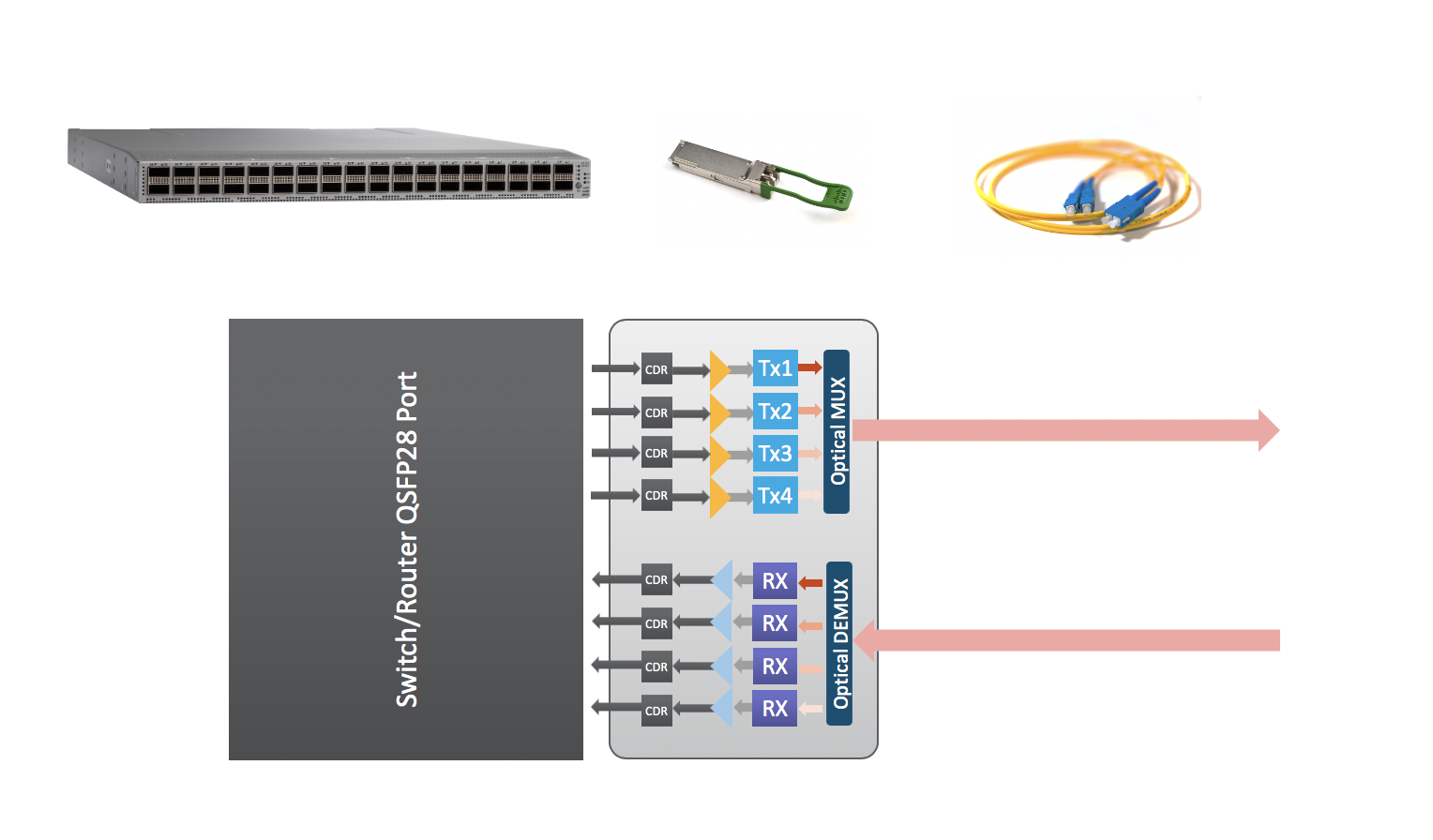
Why is it important to minimize the components in the module? Consider the diagram in Figure 1. It shows what goes into today’s 100G QSFP28 pluggable optical modules. Notice that they are inherently four-channel devices, both in the optical interface facing right, and the electrical interface facing left. Each of the four channels carries 25G of NRZ data, for a total of 100G.
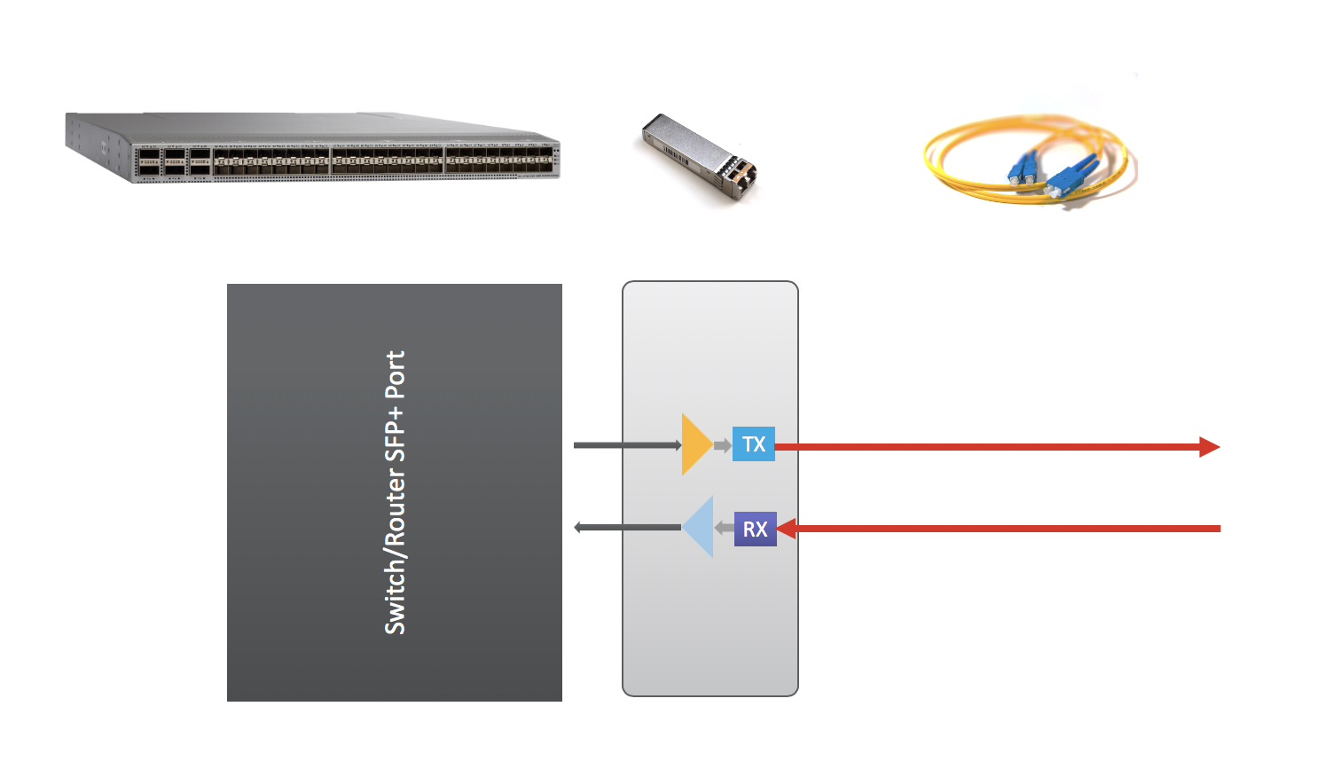
Compare this with the diagram in Figure 2, a typical 10G SFP+ transceiver. It’s pretty simple. There is only one lane that carries 10G of data. There is typically only a laser, a photodiode, and simple driver circuits for optical-to-electrical and electrical-to-optical conversion. This simplicity is key to why manufacturers are able to make 20 million 10G SFP+ modules per year.
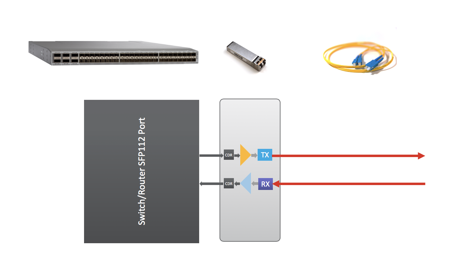
Eventually, when 100G SerDes (serializer – deserializer) is available on switch and router ports, the ASIC behind the ports can take over the FEC (Forward Error Correction) and PAM4 (Pulse Amplitude Modulation with 4 levels) functionality, leaving the pluggable module to perform only the optical-to-electrical and electrical-to-optical conversion. Then we could increase faceplate bandwidth density by using the smaller SFP form factor, with a single 100G lane on the electrical side that interfaces with the switch or router port. This form factor will likely be called SFP112 (Figure 3). Note that the block diagrams in Figures 2 and 3 look nearly the same.
We’re not there yet, though. In the meantime, we have QSFP28 modules that perform the FEC and PAM4 inside the module, as well as convert the electrical 4x25G lanes to the single 100G lane. This is what happens in our recently released QSFP28 100G FR module. The benefit of adopting this QSFP28 now is that when the SFP112 becomes available, today’s switches and routers using QSFP28 modules will interoperate with the future ones that accept SFP112 modules. And there won’t be any need for 4x25G-to-100G conversion because both the electrical interface and the optical signal will be single-lane 100G. This forward compatibility is highly advantageous for network upgrade strategies, as it prevents your existing QSFP28 modules from becoming obsolete as you add new SFP112-based hardware.
Look for more blog posts in the upcoming weeks on single-lambda 100G. Better yet, subscribe to the Cisco Optics blog!