
By this time, many of you might have followed the exciting news of the launch of commercial friendly user trial by Rakuten Mobile Network Inc. (referred as just “Rakuten” in this blog post) – the newest and the 4th mobile network operator in Japan. Rakuten Inc., the parent company, is well known in the industry as a Web and IT giant with a diversified line of businesses such as eCommerce, FinTech, rich media content and social media apps. This makes it worthwhile to note the entry of Rakuten into the telecom space with a very different background, in stark contrast with the established Communications Service Provider industry. The latter has been pursuing a content strategy to adapt to the changing market dynamics and to drive their very necessary digital transformation. The Rakuten press release and the blog post from its Chairman and CEO Hiroshi (Mickey) Mikitani-san, highlights the leadership views on the opportunity with mention of new business models, ecosystems and focus on customer experience as their key priorities.
On the technical side, while Rakuten will start its journey with LTE-Advanced technology in the radio access, they have adopted a 5G-based systems architecture for their network from day one. Virtualization and cloud native are key tenets of the 5G Systems architecture and are at the center of Rakuten’s technical strategy. They are deploying a network that is fully virtualized from RAN to Core, while leveraging mobile edge computing with end-to-end automation for both network and services. On the Radio Access Network (RAN) evolution front, this is an incredible accomplishment for the team involved and an excellent example, at scale, of what is possible with Open vRAN. Rakuten’s press release emphasizes the pivotal role of their common and distributed telco cloud platform used to host all virtualized applications. Rakuten has coined their “common and distributed telco cloud” as RCP, short for Rakuten Cloud Platform, which first appeared in a seminal LinkedIn post from Tareq Amin, the CTO of Rakuten. Cisco Systems has played a critical role from the very beginning of this exciting journey alongside Rakuten, and we could not be more proud of our partnership and collaboration. Under the hood, the RCP is powered by Cisco’s NFVI and Orchestration technologies. The purpose of this blog post is to share additional details on RCP’s design principles, architecture and technologies involved.
Let’s illustrate how RCP embraces and realizes the design principles embodied by the terms – telco cloud, common, distributed and end-to-end automation.
Telco Cloud – Essentially a private cloud in most cases to enable the realization of Network Functions Virtualization (NFV), allowing the deployment of telco applications at large scale as virtualized network functions. Examples of such telco applications for Rakuten include vRAN (vDU & vCU), vMME, vSAEGW, vIMS, vPCRF, vHSS, vDRA, vFW, vCGNAT, vCDN and more, from multiple vendors. The cloud platform requirements of these network functions across many categories are very different from traditional IT applications, thus requiring a platform engineered specifically for this environment.
From an architectural point of view, the Telco Cloud can be seen largely as a combination of two major building blocks: NFVI (NFV Infrastructure) and MANO (Management and Orchestration). These map very well into the ETSI NFV reference architecture framework.
Starting with the NFVI hardware, RCP is using standard COTS x86 servers to enable compute and storage capabilities. Intel enables a lot of those capabilities with its Xeon-SP CPU, NIC, SSD-based storage and FPGA for hardware acceleration for the vRAN workloads. Details are covered in this press release from Intel. Cisco Application Centric Infrastructure (ACI) and Nexus 9000 series of switches form the physical network fabric to interconnect all compute & storage assets and connect them back to the rest of the network. With the multi-terabit capacity, automation, service chaining, telemetry and rich policy models, Cisco ACI truly enables a 5G-ready telco data center fabric for RCP.
Cisco Virtualized Infrastructure Manager (CVIM) is a fully containerized NFVI software solution creating a cloud operating environment that forms the heart of RCP. CVIM leverages Linux/KVM-based infrastructure to enable virtual compute; Ceph for virtual storage; a combination of Open vSwitch, fd.io & SR-IOV for fast networking; docker for the management of infrastructure components – with OpenStack and soon a combination of OpenStack & Kubernetes to perform the orchestration of the cloud. Open architecture and leveraging open source technologies is a key principle of CVIM; and for that reason, it embeds Red Hat Enterprise Linux (RHEL) and OpenStack Platform (RHOSP). Almost 5 years back, we took a decision not to build our own OpenStack distribution; and rather focus our engineering efforts on building automation and tooling around OpenStack to make it easier to deploy & operate and make it more secure. That strategy has allowed us to develop numerous valuable capabilities into CVIM including: a fully automated, zero-touch provisioning installer that predictably delivers an operational cloud from the initial bare metal stage in a matter of hours; a rich set of operational tools that we developed and packaged in; extensive security hardening; fully automated & CI/CD-enabled lifecycle management capabilities to deal with ongoing maintenances including in-service updates & upgrades; extensive performance enhancement & tuning including the addition of hard Real-Time capabilities without which a Virtual RAN system would not work; 3rd party product support along with full-fledged system level pre-integration and validation. These unique characteristics bring significant value to any service provider ready to build a first-class telco cloud and made CVIM an obvious choice for RCP.
The Management and Orchestration (MANO) layer of Rakuten Cloud Platform uses Cisco Network Services Orchestrator (NSO) with the NFVO function pack as the NFV Orchestrator, and Cisco Elastic Services Controller (ESC) as the VNF manager. Cisco NSO is the industry leading orchestrator. It is model driven, has decoupled service & device models with an abstraction layer in between, and offers very strong multi-vendor support for a wide array of physical devices and virtual network functions. While there is a wide variety of interfaces support in NSO both in north and southbound directions, RCP will use the ETSI SOL003 interface for VNF-M integration. Cisco ESC will perform the role of sole Generic VNF Manager (G-VNFM) for all Cisco and most of the 3rd party workloads, providing rich VNF lifecycle management capabilities. Only one partner will use their own VNF-M integrated with NSO via a SOL003 based interface in the initial phase, and then eventually migrate onto ESC to realize the clear vision of Rakuten toward one single VNFM and one single NFVO for RCP.
The figure 1 below depicts the telco cloud architecture that builds the foundation of Rakuten Cloud Platform –
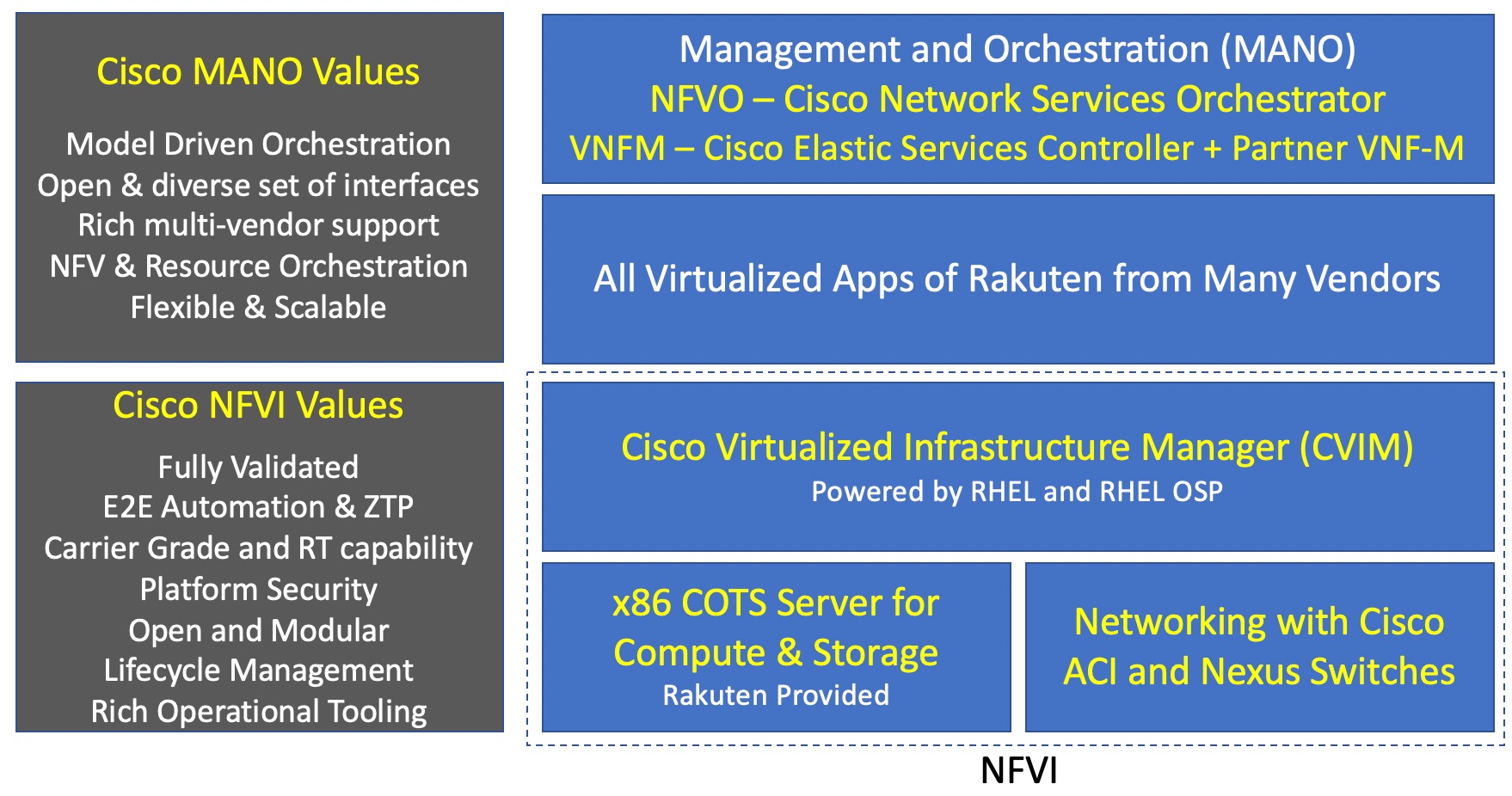
Figure 1
RCP will begin its journey as a private telco cloud by supporting all virtual network functions for Rakuten, later adding support for IT applications and expanding its reach to become a hybrid cloud platform in the future.
Common – If we dial back around 20 years in the past, Service Providers had multiple networks to support different applications. They were built using different technologies like TDM, SONET/SDH, X.25, ATM, Frame Relay, IP, and SP’s eventually realized that TCO of running multiple networks in parallel wasn’t very economical leading to the trend towards convergence on IP that we all witnessed during the first decade of this century.
Now, as the various network functions get virtualized, Service Providers in general do not want to repeat the same mistake by building multiple cloud platforms in parallel, where each of them hosts one or a subset of the target applications. The goal of these SP’s is to build a common cloud platform to host all virtual network functions from all vendors involved in their network. This will reduce cost and simplify operations while providing a repurposable infrastructure. Rakuten took a bold step in this direction by deciding from the outset to have a common cloud platform for all their applications. When compatibility issues arise with application providers on RCP, Rakuten facilitates collaboration between the parties to make sure the desired outcome gets achieved.
Distributed – A very important aspect of RCP. A Service Provider network requires a wide variety of network functions that are deployed in different “places” in the network. These places in the network would include sites such as Central DC, Regional DC, Aggregation or Central Offices, Pre-Aggregation or C-RAN Hubs, and access or Cell Sites.
If we look at a typical Central DC and/or Regional DCs of a SP, we often see the presence of network functions like the IMS Core, MME, PCRF, HSS and DRA. Packet Core gateways (e.g. SAEGW) for consumer data services are also typically located at those Central and/or Regional DCs. However, with the advent of mobile edge computing and the decomposition of SAEGW (Control and User Plane Separation), it is now possible to deploy the user plane of SAEGW (SAEGW-U) further out in the network at an aggregation or pre-aggregation location, that is closer to the consumers. Moving the user plane out in the network also allows SP’s to colocate them with content and applications in an edge computing environment supporting low latency communications and/or edge offload.
Moving further down into the network gets us to the Cell Site, where the traditional monolithic eNodeB used to reside. True to its core beliefs and disruptive streak, Rakuten is taking the market by storm as the first to deploy an Open Virtualized RAN leveraging the principles of disaggregation and decomposition of Radio Access Network layers into multiple components. The white paper we co-authored with Rakuten and Altiostar Networks talks about this decomposition in more detail. The result of that decomposition for Rakuten is a cell site, that is very lean with only Remote Radio Heads and Antennas. These cell sites will be connected via dark fiber to their respective pre-aggregation site – also called GC at Rakuten – where the virtualized Distributed Unit (vDU) processing lower layers of the radio stack and virtualized Central Unit (vCU) processing upper layers of the radio stack, will reside.
This fully virtualized network from RAN to Core, including mobile edge computing translates into a problem statement where various virtualized network functions and/or applications are required to be deployed at different locations in the network. Consequently, all those location types require the presence of the same consistent telco cloud platform, on top of which the virtualized network functions and/or applications can be deployed. In the case of Rakuten, we are pursuing three types of locations:
- Centralized Data Centers – there will be 2 in the network, and they will host key applications like vSAEGW-C, vMME, vIMS, vPCRF, vHSS, vOSS, vBSS, virtualized Gi services as well as MANO functions etc.
- Edge Data Centers at Regions/Aggregation locations – there will be somewhere around 50 or slightly less. They will host key applications like SAEGW-U, vFW/NAT, vCDN and will serve as the mobile edge computing hub for Rakuten.
- Far Edge Data Centers at Pre-Aggregation locations – there will be several thousands of them which will host the vDU and vCU applications to perform baseband/radio processing (virtualized RAN).
The figure 2 below helps to summarize the location types, key applications at each location type and an indicative scale.
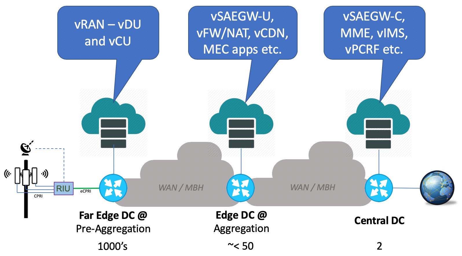
Figure 2
This may sound like a very large footprint for virtualization, and indeed it is. When the entire deployment is finished, there will be multiple thousands of locations, total server counts in 5 digits, over one million virtual CPUs, close to hundred thousand of 25GE ports coming out of all servers, and several 10s of Petabytes of storage even when the majority of the network applications aren’t storage intensive. Rakuten Cloud Platform, as a distributed telco cloud, hence can be seen as a combination of NFVIs of various sizes at thousands of locations across the network; where all of them are tied together to a centralized policy, management and automation framework. Figure 3 below illustrates this –
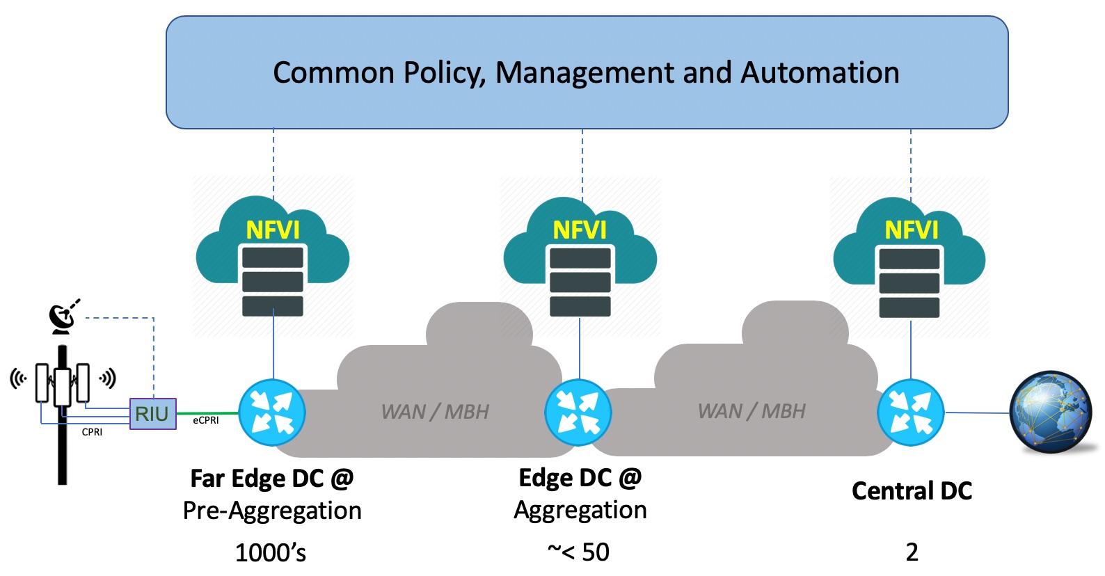
Figure 3
As we have seen before, the key applications at these three different location types vary. The scale requirement for each of these location types aren’t the same either; they vary around how many instances of each application are required, what’s the size of each instance, etc. And finally, all these three location types have different physical constraints – with the Central DC being a proper Data Center facility while the Far Edge is very constrained around space availability, limited power & cooling availability per rack, maximum equipment depth allowed etc. Catering to these requirements require different NFVI POD designs for each location type, where CVIM excels once again with a range of options providing maximum flexibility.
The Central DC locations of RCP requires 100+ racks with 1000+ servers each – so the NFVI POD design for this location type is optimized for high capacity and scale. All applications in this location uses common server hardware configuration (SKUs) to ensure operational simplicity, easy scale out and infrastructure repurpose-ability. On the storage front, depending on the application’s requirement at the Central DC, the NFVI design also includes multi-backend Ceph storage in the same POD, employing both Hark Disk Drive (HDD) and Solid-State Drives (SSD). This enables the applications requiring high storage Input-Output to leverage the SSD based backend while the others leverage the cheaper HDD based backend to drive a sound balance between cost and performance.
The Edge DC locations of RCP have much smaller footprint with respect to the number of racks of servers when compared to the Central DC. So, the NFVI POD design at these locations are balanced between footprint optimization, performance and scale. The same design philosophy of common SKUs and storage design applies to this location type as well.
The Far Edge DC locations of RCP are different in many ways. While its location constraints around space, power, cooling and rack depth have been mentioned before, this location type also has the smallest of the footprint requirements – just a few servers at each location since the target applications are only the vDU and vCU for virtualized RAN. Given there will be thousands of Far Edge DC’s in RCP, driving a major footprint optimization to minimize all overheads associated with operating a functional cloud is an essential requirement to achieve the right cost point. In order to minimize the overhead, there have been many debates and arguments in the industry. Some have presented a deployment model that consists of Centralized Control & Management Plane with only Compute nodes at the remote sites (Far Edge DC in this case), in other words a headless remote site model. For the Far Edge NFVI design for RCP, reliability and predictability were of utmost importance, and we wanted a design that would satisfy these criteria, even when the Far Edge site could be disconnected from the network or struggling to communicate with the rest of the network. Consequently, the headless model was not an option, and we took a different approach to design the Far Edge NFVI POD (One or more of the concepts presented herein are covered by one or more pending patent applications). Three main principles were established in our approach:
- Removal of Storage Service & backend from the Far Edge NFVI PODs – storage service constitutes a significant overhead in an ultra-small footprint cloud platform in terms of cost, power and ultimately maintenance; hence we removed the storage backend from the Far Edge This principle not only reduced the overhead associated with storage (CPU, memory, disk); but also helped significantly reduce the cost by removing a large volume of disk drives multiplied across thousands of sites, which would have been required if local storage backend for each site was a design goal. The virtual RAN functions (vDU and vCU) leverage ephemeral storage for the runtime in this architecture and do not require shared storage. And for the image management service, to ensure reliability and operational simplicity, we added a Common Storage Cluster just with a few servers in the design that can support thousands of Far Edge NFVI PODs. This common storage cluster is also enabled with automation and comprehensive lifecycle management capabilities.
- Sharing Control and Compute Function on the first 3 Servers in the POD and limiting the Controller Footprint with strict CPU fencing – for quite some time, CVIM has supported a deployment model that uses the same server for control and compute functions. And we do it while maintaining the same set of capabilities around HA, performance, tooling, security etc.; similar to a full-scale If done poorly, this model brings the risk that workloads and control functions fight over CPU resources, which we address by assigning specific CPUs for control functions. Any Linux system requires some CPU for the operating system (OS) and the hardware. In CVIM, we ensure that the OS is restricted to one core on each socket to ensure that workloads’ cores are not disrupted when the OS has work to do. Since the OS has to run somewhere, so this is the minimum overhead possible. We also put the control functions on those same cores and draw a hard boundary between the cores and the rest of the system, so that neither is affected by the other. Effectively, we run a local control plane on the Far Edge NFVI POD with zero overhead, which in turn allowed us to maximize resources to the vRAN workloads.
- Eventual Centralization of Management Tools – NFVI PODs today have localized software management tools to drive lifecycle management through software and hardware maintenance. Our plan is to eventually centralize those management functions as a service and eliminate the associated overhead from the Far Edge DC locations.
These key design principles ensured that each of the Far Edge DC NFVI PODs were fully autonomous with their own control plane (including their own API end-points), data plane and management plane – all done at a bare minimal footprint that has almost no overhead, yet address our goals around reliability and predictability while achieving a lower cost point. This model bears similarities with the way large scale IP networks have been built over the years, and how the IP Networking for Service Providers has evolved with Software Defined Networking (SDN). Take a look at the figure 4 below that shows an IP Network with routers at different locations. Each of those routers are fully autonomous with its own control plane, data plane and management plane, that ensures predictable and reliable operation. But with centralized management and now with SDN, we have centralized features that augment the IP network with capabilities like service orchestration (e.g. global traffic engineering), global resource management and distributed infrastructure management.
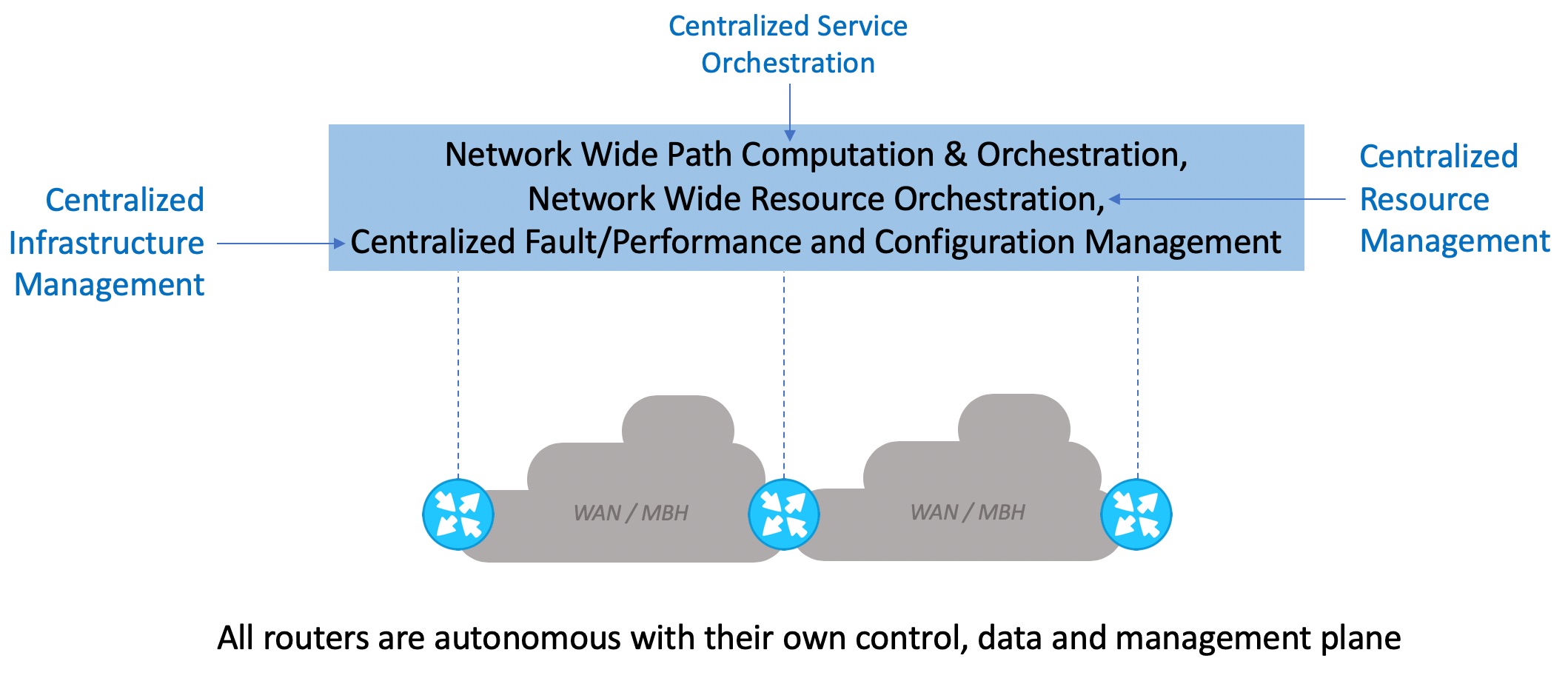
Figure 4
Applying the same principles as above gets us to our distributed telco cloud solution that powers up Rakuten Cloud Platform. The figure 5 below illustrates this. We can see that every NFVI at every location is fully autonomous with its own control, data and management plane. And it is augmented with centralized service orchestration, resource management and infrastructure management (fault, performance, logs, operational tools etc.) so that this management framework can scale in a highly distributed environment.

Figure 5
One important aspect regarding the Far Edge DC NFVI for RCP is the stringent performance requirement from the vRAN applications – particularly the vDU. The virtualized DU processes the lower layers of the radio stack and deals with digitized RF signals in a virtualized environment, which has very high throughput and extremely low latency requirement (RAN fronthaul). By comparison, think of running a TDM like application in a virtualized environment – that’s the vDU!
The end-to-end latency requirement from the air interface of the radio all the way to the vDU application is 250 micro-seconds. And that means for the virtualization environment, there are scant tens of microseconds available to move each packet from the NIC all the way into the guest user space where the Layer 1 BBU processes run within the vDU application. This low latency has to be maintained with complete certainty for every packet in a high IO throughput environment, and with no packet loss. To top it all off, everything has to be done with a server running at full load with multiple vDUs that are occupying all of its available CPU resources. This calls for an end-to-end hard Real-Time system, which we have done for CVIM. This is a significant enhancement over the standard Linux and OpenStack/KVM environment that do not guarantee this capability. We have also found that FPGA-based hardware acceleration is a requirement for the virtual DU, since then it is possible to offload certain compute intensive tasks such as error correction at the PHY layer from the general-purpose CPU. By using an FPGA, it is possible to get much higher scale (4X or more), when compared to what is achievable without it. In working with the partners, and consistent with Rakuten requirements for COTS hardware, the presentation of the FPGA is via a PCIe card. Firmware lifecycle support for the FPGA will be a capability delivered by CVIM, so that when RCP evolves to support NR (uses LPDC coding) from LTE (which uses turbo codes), the entire system, including FPGA firmware, can be upgraded automatically and with standard orchestration procedures. Complete CVIM support for open hardware platform and interfaces means there is no lock-in of the software to any of the hardware in the solution.
End-to-End Automation – managing a virtualized environment is not simple; and when you have to do that for a fully virtualized network that involves a distributed telco cloud platform like RCP spanning across thousands of sites – management at scale will be the #1 challenge that needs to be dealt with proper design, implementation and operational practices. Rakuten, Cisco and other partners involved in the project are all positively obsessed with this dimension of the project to achieve a fully automated network for both Rakuten services and infrastructure. In the previous sections, we highlighted how we are enabling a centralized management framework to manage highly distributed NFVI at scale; the Figure 6 below illustrates how the service automation framework is realized for RCP.
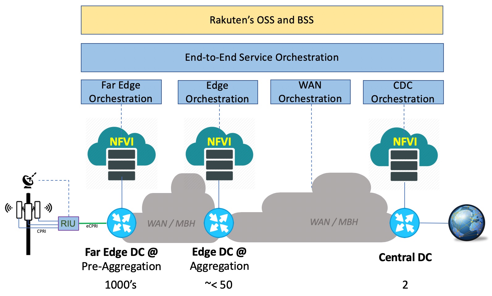
Figure 6
The service automation framework is based on the concept of hierarchical management and orchestration, and consists of four domain-level orchestration systems with full HA that manage the Central DCs, WAN, Edge DCs and Far Edge DCs. The domain-level orchestration systems are built with Cisco NSO, Cisco ESC and partner VNF-M. These orchestration systems are glued together in a modular architecture framework with an end-to-end service orchestration enabled by Cisco NSO. The service orchestration module interacts northbound with Rakuten’s OSS and BSS systems, which offer a comprehensive set of service instantiation, service lifecycle management and operational workflows.
Let’s see an example of how this end-to-end automation architecture performs zero touch instantiation of vRAN to fully operationalize a cell site with no manual intervention. The figure 7 illustrates the Zero Touch Provisioning workflow at a high level, with steps outlined below:
Step 1 – RIU at Cell site upon booting up sends up notification to the vRAN EMS
Step 2 – EMS notifies the OSS with RIU ID(s) associated to the Cell Site
Step 3 – OSS sends notification using API to NSO (E2E) asking it to activate service (new site)
Step 4 – NSO (E2E) notifies NSO (Far Edge) using API to provision vRAN VNFs
Step 5 – NSO (Far Edge) calls API to ESC to deploy vDU and vCU at the Far Edge DC
Step 6 – ESC calls CVIM API at the target Far Edge DC to instantiate vDU and vCU VNFs
Step 7 – vDU and vCU are now instantiated by CVIM
Step 8 – Upon completion of instantiation, vCU queries the EMS asking for RAN configuration
Step 9 – EMS queries OSS to get the RAN configuration and all associated parameters
Step 10 – OSS sends the RAN configuration to EMS for the new Cell Site
Step 11 – vCU receives the configuration from the EMS
Step 12 – vDU receives its configuration from the vCU
Step 13 – RIU receives its configuration from the vDU
Step 14 – All sectors are activated, and the Cell Site now becomes operational.
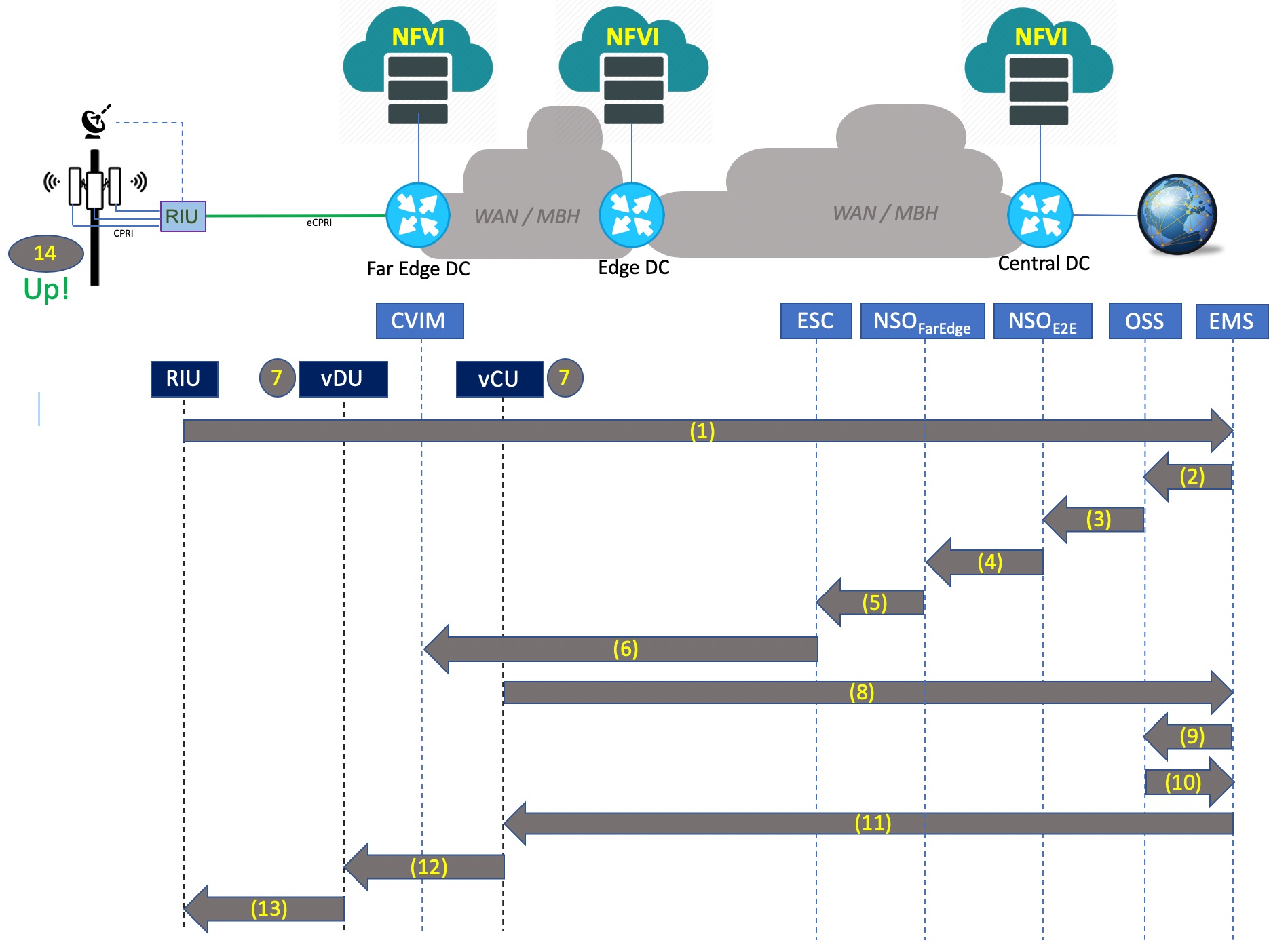
Figure 7
This is an example of a highly differentiated capability enabled by the end-to-end automation solution at Rakuten Cloud Platform, performing this activity in a matter of minutes with virtually no human involvement. In contrast, in a typical mobile network the same activity might take hours to days and involve a lot of manual work, increasing the TCO for the operator.
We hope this blog post has offered a useful perspective on how Cisco Systems and our partners have worked closely with Rakuten in a co-creation mode to turn their vision into the industry’s first fully virtualized mobile network powered by RCP, that is a common and distributed telco cloud with end-to-end automation – enabled by Cisco NFVI and orchestration solutions. If you happen to be at Barcelona at MWC 2019, please come see us at Cisco or Rakuten booth and we will be happy to discuss with you further.


Great post!
Great work Santanu!
Wonderful post! Thank you Santanu!
A technologist and a writer combined – awesome job, Santanu!
Worth reading, great post!
Excellent blog my friend. This is an excellent reference for how Cloud impacts Telco services today.
Good one Santanu !
great post. End to end architecture, different Cisco products involved ..very well explained
Clear and concise writeup and highly informative. Useful links add value.
I emphasize on transport as separate industry, like cloud, from the point of cloud overlay network. I think that would be a critical area for success of e2e cloud native telecom arch.
my LI -https://www.linkedin.com/in/saurabhverma-india/
Great post, thanks for sharing.
Nice Article on how e2e automation helps bring up the Radio.
Nicely written with good insights
Exceptionally well!! Nice high level articulation..
Nice doc.
BTW, what's the full form of RIU?
RIU stands for Radio Interface Unit. Essentially its a eCPRI gateway that takes multiple option 8 CPRI based interface inputs and converts them into a single Option 7 based eCPRI output (i.e. converting Time Domain IQ samples into Frequency Domain IQ sample)
Excellent one Santanu.