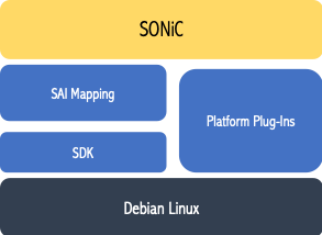
Since its introduction by Microsoft and OCP in 2016, SONiC has gained momentum as the open-source operating system of choice for cloud-scale data center networks. The Switch Abstraction Interface (SAI) has been instrumental in adapting SONiC to a variety of underlying hardware. SAI provides a consistent interface to ASIC, allowing networking vendors to rapidly enable SONiC on their platforms while innovating in the areas of silicon and optics via vendor-specific extensions. This enables cloud-scale providers to have a common operational model while benefiting from innovations in the hardware. The following figure illustrates a high-level overview of the platform components that map SONIC to a switch.
SONiC has traditionally been supported on a single NPU system with one instance of BGP, SwSS (Switch State Service), and Synced container. It has been recently extended to support multiple NPUs in a system. This is accomplished by running multiple instances of BGP, Syncd, and other relevant containers, one per NPU instance.
SONiC on Cisco 8000
As part of Cisco’s continued collaboration with the OCP community, and following up on support for SONiC on Nexus platforms, Cisco now supports SONiC on fixed and modular Cisco 8000 Series routers. While the support for SONiC on fixed, single NPU systems is an incremental step, bringing in another cisco ASIC and platform under SONiC/SAI, support for SONiC on a modular platform marks a significant milestone in adapting modular routing systems to support SONiC in a fully distributed way. In the rest of the blog, we will look at the details of the chassis-based router and how SONiC is implemented on Cisco 8000 modular systems.
Cisco 8000 modular system architecture
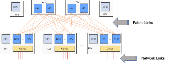
Let’s start by looking deeper into a Cisco 8000 modular system. A modular system has the following key components – 1) One or two Router Processors 2) Multiple Line Cards 3) Multiple Fabric cards 4) Chassis commons such as FANs, Power Supply Units, etc. The following figure illustrates the RP, LC, and FC components, along with their connectivity.
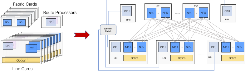
The NPUs on the line cards and the fabric cards within a chassis are connected in a CLOS network. The NPUs on each line card are managed by the CPU on the corresponding line card and the NPUs on all the fabric cards are managed by the CPU(s) on the RP cards. The line card and fabric NPUs are connected over the backplane. All the nodes (LC, RP) are connected to the external world via an Ethernet switch network within the chassis.
This structure logically represents a single layer leaf-spine network where each of the leaf and spine nodes are a multi-NPU system.
From a forwarding standpoint, the Cisco 8000 modular system works as a single forwarding element with the following functions split among the line card and fabric NPUs:
- Ingress line card NPU performs functions such as tunnel termination, packet forwarding lookups, multi-stage ECMP load balancing, and ingress features such as QoS, ACL, inbound mirroring, and so on. Packets are then forwarded towards the appropriate egress line card NPU using a virtual output queue (VOQ) that represents the outgoing interface, by encapsulating the packet in a fabric header and an NPU header. Packets are sprayed across the links towards the fabric to achieve a packet-by-packet load balancing.
- Fabric NPU processes the incoming fabric header and sends the packet over one of the links towards the egress line card NPU.
- Egress LC NPU processes the incoming packet from the fabric using the information in the NPU header to perform the egress functions on the packet such as packet encapsulation, priority markings, and egress features such as QoS, ACL and so on.
In a single NPU fixed system, the ingress and egress functions described above are all performed in the same NPU as the fabric NPU functionality obviously doesn’t exist.
SONiC on Cisco 8000 modular systems
The internal CLOS enables the principles of leaf-spine SONiC design to be implemented in the Cisco 8000 modular system. The following figure shows a SONiC based leaf-spine network:
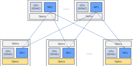
Each node in this leaf-spine network runs an independent instance of SONiC. The leaf and spine nodes are connected over standard Ethernet ports and support Ethernet/IP based forwarding within the network. Standard monitoring and troubleshooting techniques such as filters, mirroring, traps can also be employed in this network at leaf and spine layers. This is illustrated in the figure below.
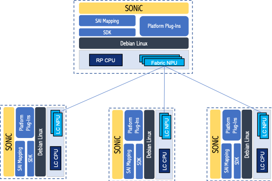
Each line card runs an instance of SONiC on the line card CPU, managing the NPUs on that line card. One instance of SONiC runs on the RP CPU, managing all the NPUs on the fabric cards. The line card SONiC instances represent the leaf nodes and the RP SONiC instance represents the spine node in a leaf-spine topology.
The out-of-band Ethernet network within the chassis provides external connectivity to manage each of the SONiC instances.
Leaf-Spine Datapath Connectivity
This is where the key difference between a leaf-spine network and the leaf-spine connectivity within a chassis comes up. As discussed above, a leaf-spine network enables Ethernet/IP based packet forwarding between them. This allows for standard monitoring and troubleshooting tools to be used on the spine node as well as on the leaf-spine links.
Traditional forwarding within a chassis is based on fabric implementation using proprietary headers between line cards and fabric NPUs. In cell-based fabrics, the packet is further split into fixed or variable sized cells and sprayed across the available fabric links. While this model allows the most optimal link utilization, it doesn’t allow standards-based monitoring and troubleshooting tools to be used to manage the intra-chassis traffic.
Cisco Silicon One ASIC has a unique ability to enable Ethernet/IP based packet forwarding within the chassis as it can be configured in either network mode or fabric mode. As a result, we use the same ASIC on the line cards and fabric cards by configuring the interfaces between the line card and fabric in fabric mode while the network-facing interfaces on the line card are configured in network mode.
This ASIC capability is used to implement the leaf-spine topology within Cisco 8000 chassis by configuring the line card – fabric links in network mode, as illustrated below.
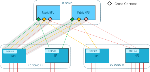
SONiC on the line cards exchange routes using a per NPU BGP instance that peers with each other. SONiC on each line card thus runs one instance of BGP per NPU on the line card, which is typically a small number (low single digits). On the other hand, RP SONiC manages a larger number of fabric NPUs. To optimize the design, fabric NPUs are instead configured in a point-to-point cross-connect mode providing virtual pipe connectivity among every pair of line card NPUs. This cross-connect can be implemented using VLANs or other similar techniques.
Packets across the fabric are still exchanged as Ethernet frames enabling monitoring tools such as mirroring, sFlow, etc., to be enabled on the fabric NPUs thus providing end-to-end visibility of network traffic, including the intra-chassis flows.
For the use cases that need fabric-based packet forwarding within the chassis, the line card – fabric links can be reconfigured to operate in fabric mode, allowing the same hardware to cater to a variety of use cases.
In summary, using the unique capabilities of the Cisco Silicon One ASIC and the system design, Cisco 8000 allows implementing SONiC based standard leaf-spine network topology within a modular system, paving the way to achieve the flexibility of a disaggregated network design at the optimal cost and power envelope of a modular system.
For more information on running SONiC on Cisco 8000 click here.