
Contributors – Ming Chong and Santa Chowdhury (octoScope)
We are particularly grateful to Nilesh Doshi (Sr. Wireless AP Manager) for his supervision.
Servicing many clients that are using small packets with non-Wi-Fi 6 is inefficient because the overheads incurred by the preamble and other mechanisms tend to dominate. OFDMA is ideally suited for this scenario because it divides up the channel and services up to 37 users (for 80MHz bandwidth) simultaneously, which amortizes the overhead. OFDMA improves system efficiency, but it does not necessarily improve throughput.
MU-MIMO (Multi-User, Multiple input, Multiple output) creates spatially distinct separate channels between the transmitter and each of a small number of receivers such that each receiver hears only the information intended for itself, and not the information intended for other receivers. This means that the transmitter can, by superposition, transmit to a few receivers simultaneously, increasing the aggregate throughput by a factor equivalent to the number of receivers being serviced.
Cisco’s Catalyst 9800 series WLC with IOS XE 17.6.1 (currently Beta) introduces futuristic Access Point scheduler design, which efficiently serves multiple clients at the same time. This is done while creating least level of sounding overhead, which in turn yields data rates close to PHY rate even in dense environment. These advancements are currently supported on Catalyst 9130 and Catalyst 9124 series Access Points. Let’s first understand MU-MIMO concepts and then evaluate its performance.
Beamforming and MU-MIMO
Beamforming radio waves using an array of phased antennas has been known for decades. More recently the principles have been used to produce MU-MIMO where the concept of multiple simultaneous beams to provide independent channels for each of the users.
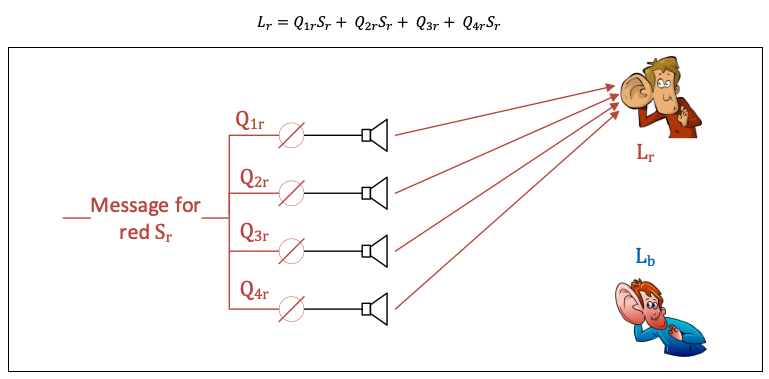
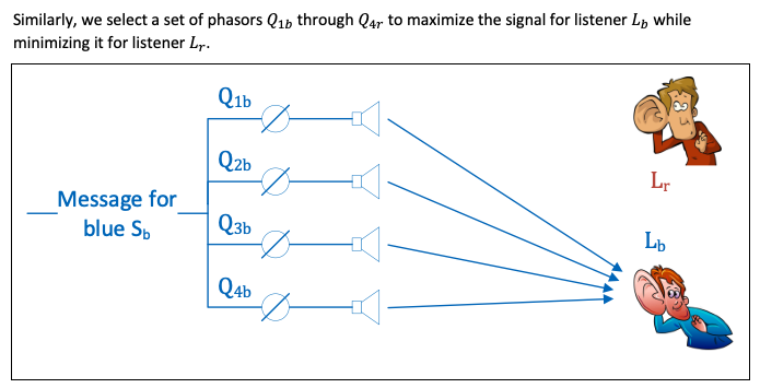
Similar principles apply in the audio domain where speakers can be phased to direct sound to a particular location. The idea is to adjust the phases of each speaker such that the sound adds constructively at the point where the listener is, and destructively at all other locations.
Consider a sound, Sr , played through an array of four speakers with the sound for each speaker adjusted by a phasor Q1r through Q4r so that the signal strength at the red listener, Lr is maximized, and the signal strength at the blue listener Lb is minimized.
Using superposition, we can take each message, impose the appropriate phase adjustment, and add the signals just before they go into the speakers. This way we can send two different messages at the same time, but each listener will hear only the message intended for them.
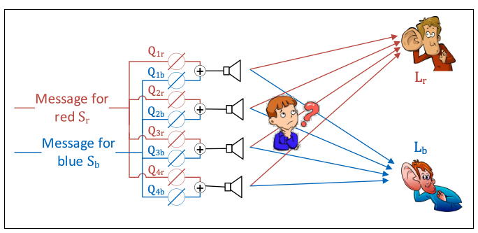
Note the importance of spatial separation – Lb and Lr are hearing their respective messages because the phasors were optimized to deliver each sound to their specific location. If one of the listeners moves from his position, he will no longer hear his message.
If a third person enters the picture and stands close to the speakers, he will hear the garbled sound of both messages simultaneously.
Consider this in the context of Wi-Fi where the speakers are replaced by antennas and the signal processing to control the phasors, and generate digital messages at a certain data rate, is done in the AP. Since both messages can be transmitted simultaneously one could theoretically double the aggregated data rate. The same approach can be used to service more clients simultaneously, so where is the limit? Practically, there are limits in the accuracy that the phasors can be set, there are reflections that cause “cross talk” and other imperfections that limit the gains in throughput that can be achieved.
Sniffing in the context of MU-MIMO is more complicated because of the spatial significance. Note that placing a sniffer close to the AP will achieve the same garbled message effect we discussed earlier. The sniffer probe must be placed physically close to the device that is being sniffed, and generally one sniffer probe is required for each device.
System Overview and Test infrastructure
In this MU-MIMO test, we are using the octoScope (now part of Spirent) STACK-MAX testbed. On the infrastructure side, Cisco’s Catalyst 9800 WLC running IOS XE 17.6.1 (Beta code) and Catalyst 9130 Access point is used. The C9130 AP supports up to 8×8 uplink and downlink MU-MIMO with eight spatial streams. The Pal-6E is Wi-Fi 6 capable and can simulate up to 256 stations or can act as Sniffer probe.
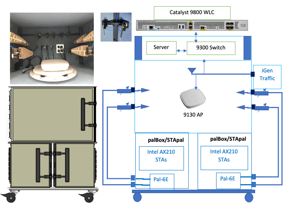
The STApal is a fully contained STA based upon the Intel AX210 chipset, running on its own hardware platform. All the test chambers are completely isolated from the outside world, and signal paths between them are controlled using fully shielded attenuators, so that reliable and repeatable measurements can be made. The chambers are lined with an RF absorptive foam to significantly reduce internal reflections and prevent standing waves.
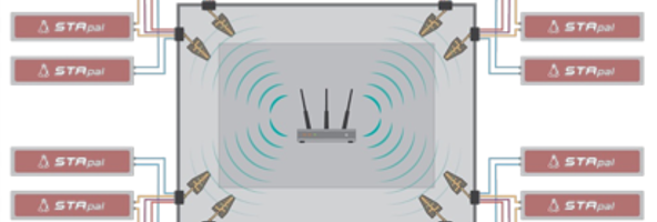
For this MU-MIMO test we are using up to 4 STA’s. RF path connects signals from the C9130 AP through to individual STAs. We are using the multipath emulator (MPE) in LOS, or IEEE Channel Model A mode. Each pair of antennas is fed into a group of four clients as shown in the diagram below. We have seen that spatial separation is a requirement for successful MU-MIMO operation. This is achieved by placing antennas in the corners of the anechoic test chamber to get the best spatial separation. This allows four independent MU-MIMO streams to STAs in the four groups of four.
Practical testing
To demonstrate the MU-MIMO gains we placed C9130 AP in the center of the chamber and ran downlink UDP traffic to the STAs attached to the antennas in the box corners.
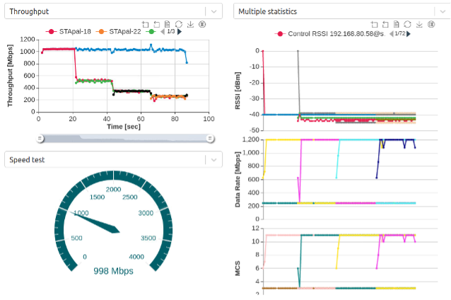
First, we did this with MU-MIMO switched off and started with one STA. We noted that the throughput was just a little over 1000 Mbps, a little less than the 1200 Mbps of the PHY rate. After 20 seconds we introduced another STA and saw that the aggregate throughput stays at the 1000 Mbps, but that the two STAs share the channel and each STA is achieving 500 Mbps. 20 seconds later we introduced a third STA. Again the aggregate throughput stays the same at 1000 MBps, and the three STAs share the channel to get a little over 300 Mbps each. Introduction of the fourth STA follows the same pattern with the aggregate remaining unchanged, and each STA receiving 250 Mbps.
We repeated the experiment, this time with MU-MIMO switched on.
Starting with one STA we achieved the familiar 1000 Mbps. After 20 seconds we introduced the second STA and observed the aggregate had increased to 2000 Mbps which is significantly higher than the PHY rate. We also noted that each STA is still receiving nearly the 1000 Mbps it was before. Unlike the previous experiment where the STAs shared the channel, in this experiment they are each able to fully utilize their own channel independently of each other.
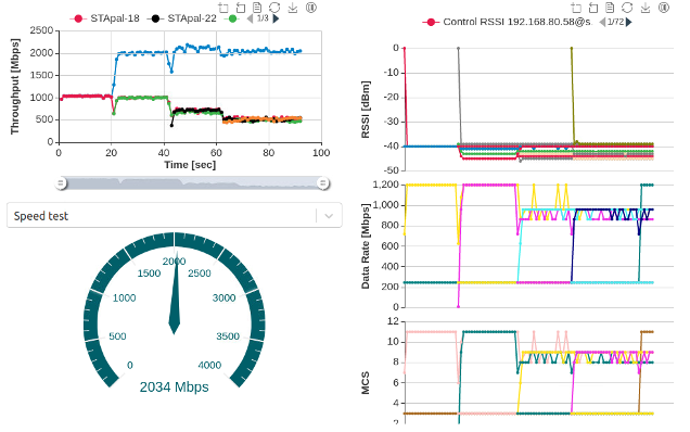
Adding a third STA increased the aggregate to 2200 Mbps. Each of the three STAs was still receiving 730 Mbps. Addition of a fourth STA results in aggregate throughput of 2100 Mbps with each STA receiving 525 Mbps, a two-fold increase over Single User operation.
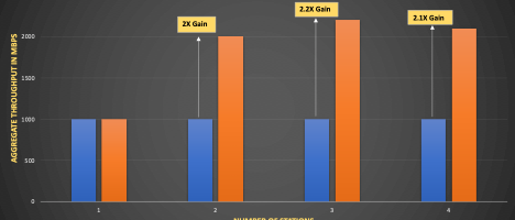
The graph below summarizes the results.
Verdict
MU-MIMO exploits the spatial separation of receivers to direct independent messages to each of the receivers simultaneously. This allows for much more efficient use of the medium and increases the aggregate data that the network can deliver. Catalyst 9130 AP’s pioneering scheduler design offers superior throughput gains in Multiuser transmission scenarios. This is an outcome of higher MCS rates, low sounding overhead and efficient dynamic packet scheduling.
DL and UL MU-MIMO along with OFDMA are enabled by default on a WLAN. These features are available on 9800 series wireless controllers on existing releases but the above discussed enhancements will be available from 17.6.1 (currently Beta) release onwards.
Learn more about Catalyst 9100 series Access Points and Cisco Catalyst 9800 Wireless Controllers.
Check out our Cisco Networking video channel