Here at Cisco’s DevNet IoT (Internet of Things) group, our team of experts is constantly seeking innovative ways to incorporate technologies from different areas around the world with Cisco’s cutting-edge IoT-capable platforms and devices. In response to recent events, we’ve created an IoT IR Thermal Camera that reads body temperature and provides instant feedback regarding if a subject’s temperature is within the normal range.
Project background
This project guides the user through the process of creating an IoT IR Thermal Camera to be deployed on Cisco Edge Devices, such as the IR829 Router. During these times, a body temperature reading can give us peace of mind and allow us to better navigate and operate in the present. It is economically prohibitive for most people and small businesses to screen others for the main measurable symptom of COVID-19, which is high body temperature, or “fever.” The current IR temperature scanners on the market are neither network nor power connectable. And, they are not calibrated to measure human body temperature.
We developed this project as a way to use commercially available materials and Cisco’s IoT platform to develop a solution. You can review my entire project at this repo.
Project goal
This project started as a research mission to determine the feasibility of deploying an IR thermal camera on an edge device and managing it remotely from the cloud. Our goal is ultimately to enable Cisco partners and customers to create similar projects for their own use, or to bring to market.
As stated previously, we determined the commercial market currently lacks hand-held commercial off-the-shelf (COTS) temperature scanners, except those which are a) battery-operated b) designed for industrial use (not for body temperature), or c) unable to connect either wired or wirelessly (save for a few models which have Bluetooth connectivity only). Any one of these attributes precludes these devices for use in our mobile human temperature screening project.
The initial requirements and specifications include:
- The system must be portable. The entire system (scanner, router, display and power source) should be able to be transported in a personal carrying case and operated wherever a power outlet and cellular signal are present.
- We wanted to use commercially available products such as a Raspberry Pi 4 and an incorporated IR Thermal Camera to collect temperature
- To leverage IoT, we wanted to extend the range of the thermal data collection by hosting our project software in the IR829 router’s IOx VM and OS, which will contain and manage the Thermal Camera and collect data from it.
- Because this is a portable solution, we had to create a durable and mobile case to house the Raspberry Pi, thermal camera, IR829 and associated peripherals.
Putting the Sensor Together
In this first part of the series, I describe the steps to put together the Pi and camera.
- Purchase and set up a Raspberry Pi. We procured a Raspberry Pi 4B that included heat-sinks, a case, and extra wiring (electrical, HDMI, Cat 6, etc.). Raspbian was already preloaded onto the SIM card included in the set. Set up the Pi with a monitor, keyboard, and mouse and make sure it is secure.
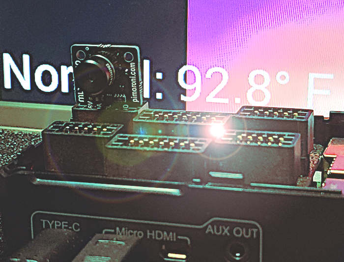
- Purchase a MLX90640 IR Thermal Camera. Adafruit and Pimoroni are among the most well-known distributors, but they were all sold out. We ended up ordering a Pimoroni from eBay for around $100 USD, which is roughly double the normal, non-pandemic price. I saw some who tried this project previously had used an 8 X 8 array of IR thermal sensors, which produced a display which lacked detail and granularity. The main reason I chose the MLX90640 is because it offers a much better 24×32 array of IR thermal sensors. You can find the data sheet here and a GitHub repo with related code here.
- Attach the IR Thermal Camera to the Raspberry Pi. There are two ways to do this and each has their advantages:
A) Solder the camera to the Pi (you are now a computer engineer, yay!), which requires more time and skill but gives you more control over how you want to position the camera in relation to the Pi.
B) Purchase a Breakout Garden for your Raspberry Pi. This makes adding the IR Thermal Camera, as well as many other sensors and peripherals rather easy, but does limit the directions you can point your sensors. It also eliminates the ability the fully integrate the case, including fan, which was designed for the Raspberry Pi without Breakout Garden on top.
Our IR Thermal Camera is now operational locally. I converted from Celsius to Fahrenheit and display both temperature scales. We won’t see our body temperature near 98.6 Degrees F as our skin dissipates some of the heat that can be read by the IR Scanner. We do, however, see a display of “Normal”, indicating our body temperature is within the acceptable range for healthy human beings.
The code for this project is now also on Cisco DevNet Code Exchange:
Future Considerations
In the next part of this series, we will explore how I tested software to get the most accurate temperature readings and how to deploy the solution on the Cisco IR829 router.
References:
- MLX90640 IR Thermal Camera data sheet
- MLX90640 IR Thermal Camera code repo
- Raspberry Pi data sheet
- Securing your Raspberry Pi. (2020). Retrieved from RaspberryPi.org
- Stevenson, A. Skin Temperature Scanner GitHub repo
Related resources:
- Learn more about Cisco IoT technologies and get developer resources, visit the DevNet IOT Dev Center
Thanks for reading. If you have comments or questions, please leave me a comment in the space below. And stay tuned for the next blog in this series: “Test software to get accurate temperature readings and deploy on a Cisco IR829.”
We’d love to hear what you think. Ask a question or leave a comment below.
And stay connected with Cisco DevNet on social!
Twitter @CiscoDevNet | Facebook | LinkedIn
Visit the new Developer Video Channel