In part 1 of this blog series, we overviewed the different tools that would be used as you go up the stack from infrastructure to application. In part 2, we provisioned the Infrastructure as Code (IaC) using Terraform, Ansible, Jenkins and GitHub. In this blog, we will go over how to deploy Infrastructure as Code (IaC) using GitOps.
GitLab defines GitOps as an operational framework that takes DevOps best practices – used for application development such as version control, collaboration, compliance, and CI/CD tooling – and applies them to infrastructure automation.
We will leverage Jenkins as our CI/CD tool to build and automate the Terraform and Ansible configurations. The code will be committed to the infra branch in our GitHub repository, Cloud Native Security SPOT ON Series. We will then create a pull request to merge the infra changes into the main branch and confirm the merge. If you remember from our last episode, when we setup our multibranch pipeline in Jenkins, we set the configuration to poll the main branch every minute, and if there were any changes to trigger the pipeline. Since we are adding new code to main branch, Jenkins will trigger the pipeline.
The first thing that happens is Jenkins will check out the code from our GitHub repository and add it to the Jenkins agent, in this case the Jenkins Master. After that it runs a “terraform get –update“. This updates any new modules added to the configuration. Then it runs a “terraform init,” which will initialize all the Terraform Providers. Finally, “terraform apply” is run to do the deployment. This will pass all the variables from Jenkins to Terraform. The run takes about 20 minutes because we are provisioning an EKS cluster and a Secure Firewall instance which take time to spin up. In total, there will be 48 resources deployed to our AWS environment. We will also get output from Terraform which gives us the EKS Cluster name and API, as well as the EKS Worker Node and Secure Firewall Management public IP addresses.
Once the build is complete, we can verify using the AWS Dashboard and Firepower Device Manager. First, we will check the AWS VPC Dashboard and we will see a new VPC, with 5 subnets, 2 route tables, 1 internet gateway, and 2 elastic IP addresses. Next, we check EC2 Dashboard and find 2 instances, one for the Secure Firewall and the other for the EKS Worker Node. Then we go into the EKS Dashboard, and we will see a Kubernetes cluster with the EC2 worker node assigned to it.
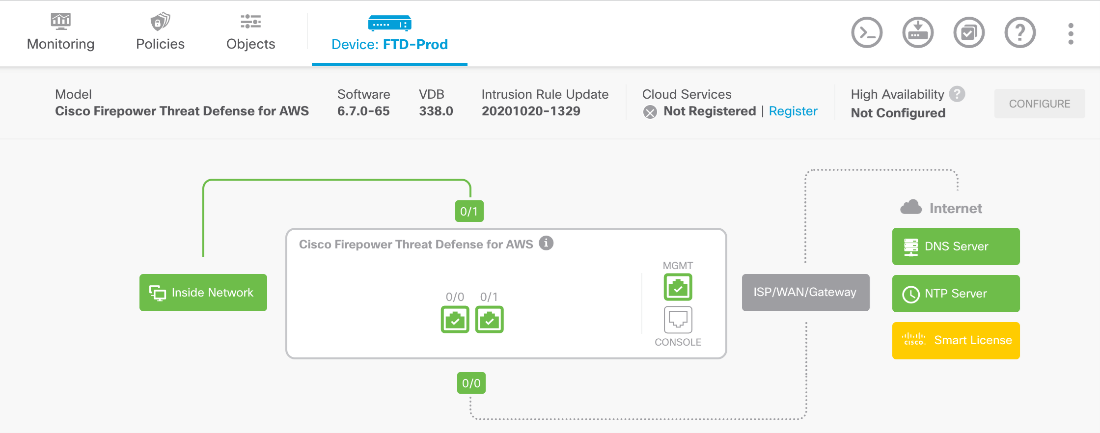
Next, we jump into the Firepower Device Manager (FDM) to validate our NGFW (Next Generation Firewall) configuration. To access the FDM we use the IP address generated from the Terraform output. We will see that the interfaces have been configured with IP addresses and security zones, internal and external routes have been applied, network and service objects have been created, access control list has been deployed and inbound and outbound rules have been configured, and network address translation has been assigned for the EKS node.
For detailed output of all these steps, please read on below
Check out the demonstration below:
Cisco Secure Cloud Native Security – Part 1.2 – GitOps and CI/CD
Detailed Output
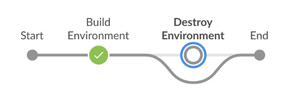
After the code has been merged into the main branch, the Jenkins pipeline will be triggered.
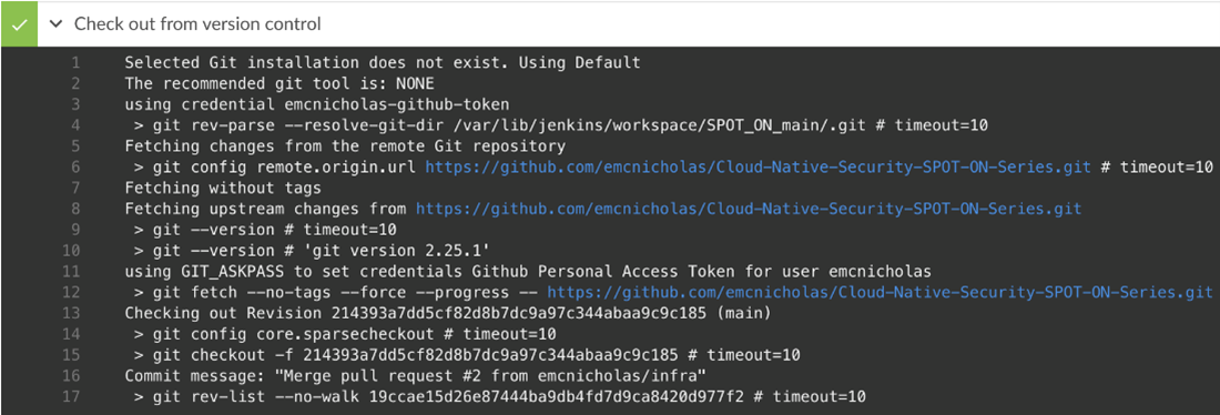
Step 1, Jenkins checks out the code from the GitHub repository.
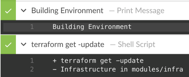
Step 2 prints out “Building Environment.”
Step 3 runs “terraform get –update” which updates the modules. In this case, it updates the infrastructure module.
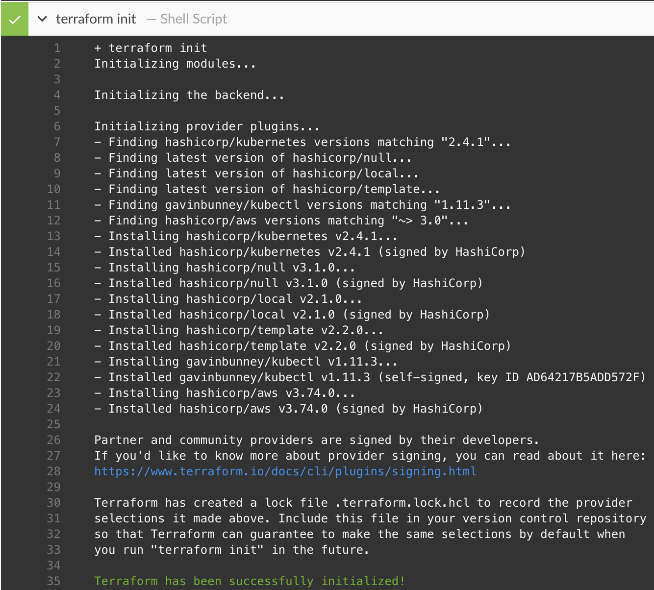
Step 3 run “terraform init”, which will initialize all the providers.
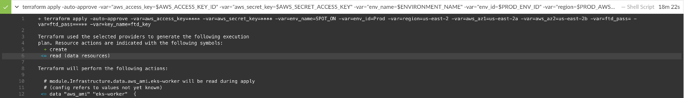
Step 4 runs “terraform apply –auto-approve” passing all the variables.
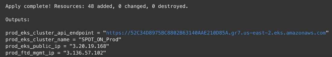
The run is complete showing 48 resources have been added and the outputs of the EKS API, EKS cluster name, EKS worker public IP address, and the FTD Mgmt. IP address.
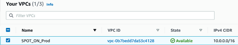
In AWS VPC Dashboard, we see a VPC named SPOT_ON_Prod.
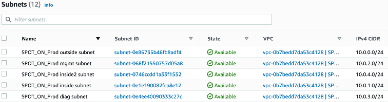
There are 5 subnets assigned to the VPC.
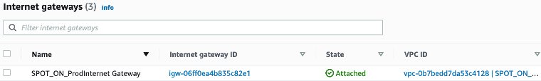
There is 1 internet gateway.
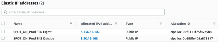
There are 2 Elastic IP addresses, one assigned to the EKS worker node, and another assigned to the FTD Mgmt. interface.
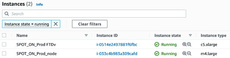
There are 2 EC2 instances, one hosting FTD the other EKS Worker Node.
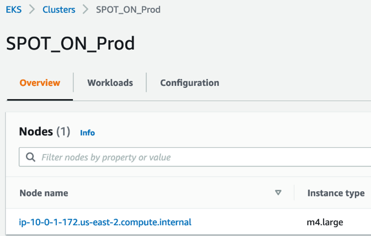
There is 1 EKS Cluster with the Worker Node EC2 instance assigned to it.
We access the Secure Firewall via the Firepower Device Manager Mgmt IP address that we got from the Terraform output.
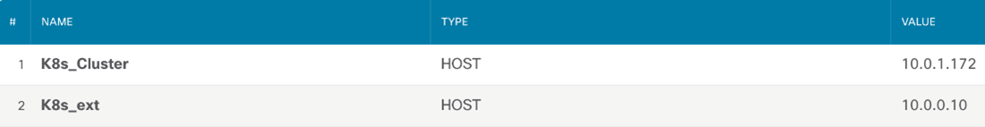
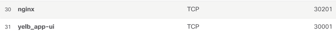
Below we see the Network Objects configured for the EKS worker node and the Service Objects for the Yelb and NGINX applications.
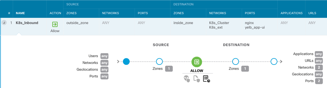
Here is the inbound access rule that allows ANY to the EKS worker node for service ports of our apps.
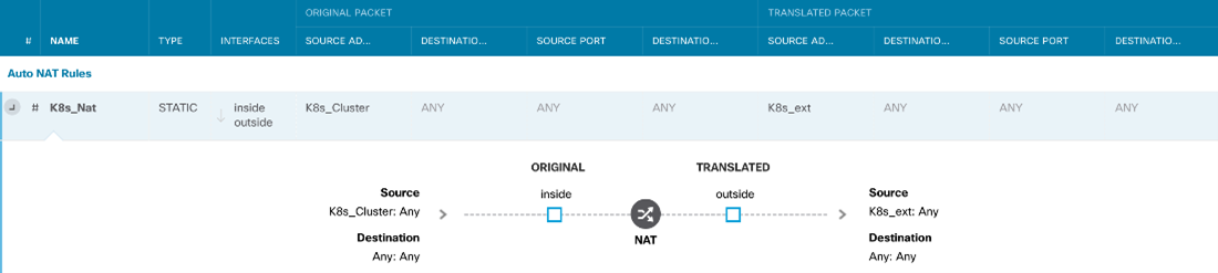
This is a static NAT so the outside world can access the EKS node.
We’d love to hear what you think. Ask a question or leave a comment below.
And stay connected with Cisco DevNet on social!
LinkedIn | Twitter @CiscoDevNet | Facebook | Developer Video Channel