Earlier blogs have covered PnP use cases for simple deployments of a single switch. This blog covers the design and automated deployment of a complete branch infrastructure. There will be no need to connect to the Command Line Interface (CLI) of any device.
Topology
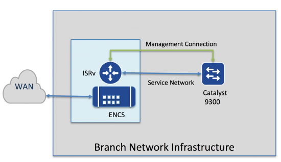
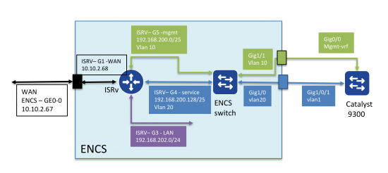
In this example, Enterprise Network Compute Server (ENCS) is used to host the virtual network function(s). This simple example has only a single function, an ISR router (ISRv). This could easily be extended to include Cisco and third party virtual network functions.
The example shows automated provisioning of both virtual (ISRv) and physical (Catalyst 9300). There are two connections between the ISRv and the 9300. This could be simplified, but the two connection model provides all choices of connections between the ENCS running ISRv and the 9300 (L2, L3, PortChannel, ECMP etc).
Process
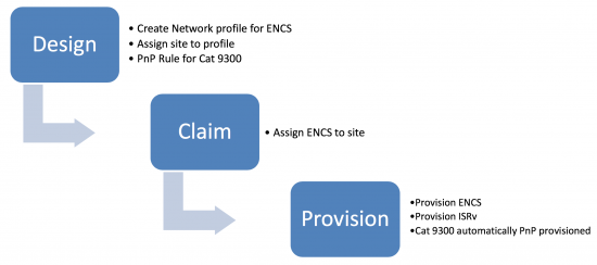
DNA Center provides the automation tools for this deployment. There are three main steps illustrated below:
- Design phase. This is where IP address pools, site specific settings like credentials, DNS, AAA are defined. In addition a network profile is defined, which include the “design” of the ENCS network functions and their internal network connectivity. Finally, the network profile is mapped to one or more “sites.” Site hierarchy is also defined in this phase.
- Once the device is connected to the network, it uses PnP to discover the DNAC and will appear as an “unclaimed” device. The “claim” process simply assigns the device to a site.
- Once the device is assigned to a site, it can be provisioned. This step places any device specifc settings (for example interfaces). Most of this information has already been defined in the design, so cannot be changed. The ISRv is also provisioned, but there is very little to change. Once the WAN services are up, the Catalyst 9300 automatically uses PnP to obtain it’s configuration.
Example
This example assumes the design has been complete (just to show how simple it is). I will come back to the design later on.
Claim Step
This example assumes a new ENCS device has been connected to the WAN, and it is able to discover DNA Center. It will appear as an unclaimed device under the provisioning workflow. Provision -> Unclaimed Devices
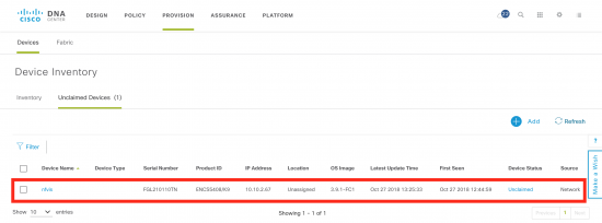
Next step is to select the nfvis device (nfvis is the default name for the device), and claim it. All that is required is a site, in this example “Brisbane”. Click Apply.
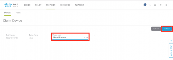
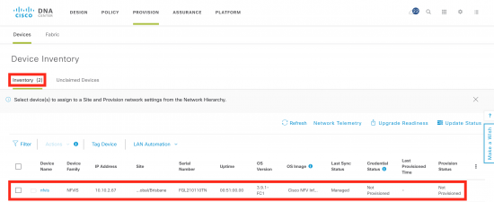
Click on the inventory tab, and you will soon see the device added to inventory, but in the “unprovisioned” state.
Provision Step
Now to provision the ENCS based on the network profile in the design phase.
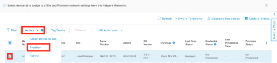
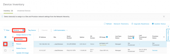
Select the device, then go up to the “Actions” menu and select “provision”. This will begin the provisioning workflow.
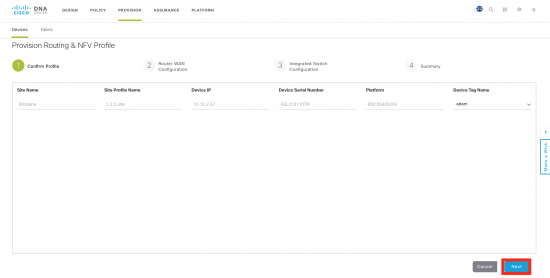
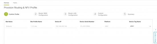
In the first step, there is little to do, unless you are provisioning multiple devices at once. The main thing to remember is the “Next” button at the bottom of the screen to progress to the next step.
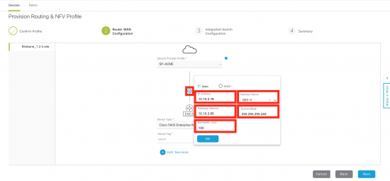
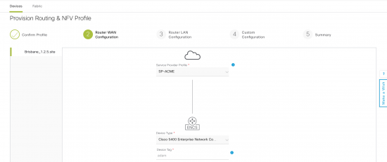
Step 2 (router WAN) is where the WAN interface for the ISRv is done. Click on the small circle that links the ENCS to the WAN. Then fill in details for the IP address, WAN interface on ENCS, and bandwidth.
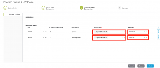
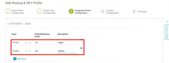
Step 3 is the Integrated Switch configuration. ENCS has built in switch with up to eight ports. In this example there are internal networks map to the two vlans. In this example, vlan 20 (service) is mapped to the service-net on ISRv and exposed on interface GigabitEthernet1/0 on the ENCS switch. Similarly, vlan 10 mapps to mgmt-net and interface GigabitEthernet1/1 on the ENCS switch.
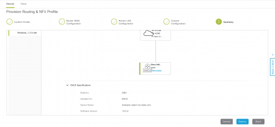
The final step is to review and deploy.
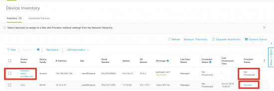
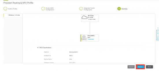
After a short period of time, the ENCS will be provisioned, which will create all of the internal networking and spin up the ISRv, and add it to the inventory. You can check on the status of the provisioning by clicking on the hotlink on the far left of the ENCS entry. Note also the ISRv is added, but not yet provisioned.

Provisioning ISRv
The same workflow is followed for configuring the ISRv. In this example a pre-defined configuration template will be applied. The template was defined and applied during the design phase. This is exactly the same workflow as with the ENCS.
Firstly, select the ISRv, goto actions and select provision.
Step 1 is just a preview.
Step 2 is the router WAN configuration. Again there is nothing to configure here as WAN configuration was done in the ENCS workflow.
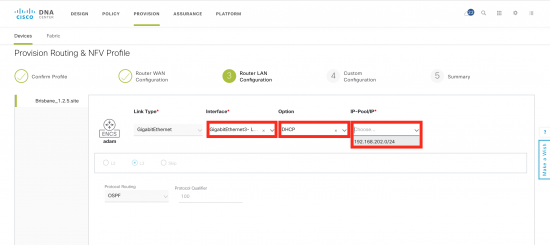
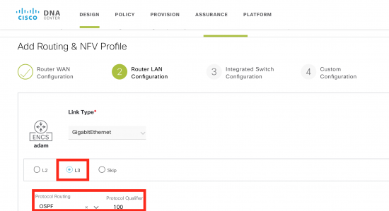
Step 3 is the Router LAN configuration. In this deployment, the router has a layer three connection (routed, OSPF) to the downstream Cat 9300, so this is not really required. In this case Gig3 appears in the dropdown menu as it has a “LAN” tag. Just select DHCP and the single address pool. These come from the ENCS configuration.
Due to the deployment model (the service network is going to be used to connect to the switch, rather than the LAN network), these settings do not really matter. In other deployment models, they are.
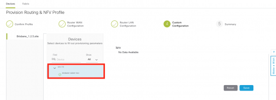
Step 4 is the custom configuration template. In this example, there are no device specific variables in the template. If there were, they would be filled in here.
Final step is to review and deploy.
Once deployment starts, it can be monitored in the same way as ENCS.
The end result is the ISRv will be deployed, and due to the DHCP configuration on the device, the Catalyst 9300 will also use PnP to automatically provision based on a pre-defined rule. There are now three devices in the inventory. You will notice the ISRv is “Out of date” as I made some changes to the configuration template post-deployment. The 9300 is not fully provisioned as it has a day 0 configuration.
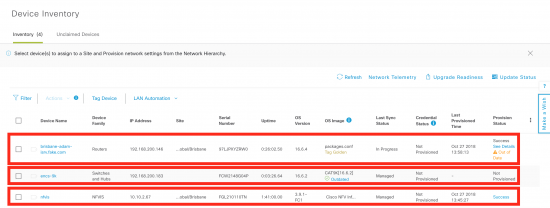
I now have a fully deployed branch.
Details
This section shows the detailed configuration and how to define the network profile, along with ENCS/ISRv templates. The templates augment the base configuration.
There are options where a single connection can be used to connect the 9300 and the ENCS. In this scenario, there are limitations around topology (for example port channel will not auto-negotiate). Using the management interface to PnP provision the switch, means any configuration can be applied to the front panel ports, without needing to establish connectivity first.
For example in the L3 connection, there is no default route provided to the 9300. It can only communicate to the outside world once OSPF is configured and comes up via the front panel ports.
In this case the service network and the management networks are being used and the LAN network is not required. When other services such as firewall are used, the services network would link the router and the firewall and the LAN interface connect to the firewall.
The complete topology is configured via a network profile, and fully automated by DNA Center.
Design
IPAM
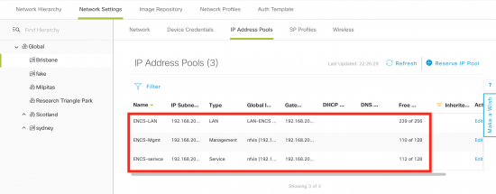
Three IP address pools are required for provisioning. They are:
- LAN for the LAN network.Typically this will be the connection to the end user devices. As I am using a L3 link to the 9300 switch, the Lan networks will be terminated on the 9300, and this network is not being used.
- Service for the service network.In this example this will be a L3 connection to the 9300 switch. In other topologies it will be used to link services such as Firewall into a chain.
- Management for the management network.Note, the management IP address is used to discover the ISRv router, so there needs to be reachability to it.
The current subnet masks are very generous, and would be optimized depending on the deployment scenario.
Templates
While most of the ENCS configuration is automated, extra configuration can be supplied in a template. This allows capabilities that are not supported in the design workflow to be implemented. For example PortChannel on the switch ports. Currently, the switch vlan are used, but not defined via the design. The ‘encs’ template contains these extra commands.
switch vlan 10
switch vlan 20
This template is used to configure the ISRv router. This is an extension to the base configuration, which includes everything to make the router discoverable by DNA Center. Although ospf is configured on the router, we need to change the networks that are advertised. DHCP scopes to allow PnP for the switch and the service interface for the 9300 switch are also defined.
router ospf 100
network 10.10.2.0 0.0.0.255 area 0
no network 192.168.200.0 0.0.0.255 area 0
network 192.168.200.0 0.0.1.255 area 200

ip dhcp excluded-address 192.168.200.129 192.168.200.180
!
ip dhcp pool PnP-mgmt
 network 192.168.200.128 255.255.255.128
 default-router 192.168.200.146
 option 43 ascii "5A1N;B2;K4;I10.10.10.181;J80"

ip dhcp excluded-address 192.168.200.1 192.168.200.60
!
ip dhcp pool PnP-service
 network 192.168.200.1 255.255.255.128
This is the configuration template for the 9300 switch. This template will be used in a PnP rule.
hostname $hostname
vtp mode off
enable password cisco
username cisco privilege 15 password 0 cisco123

interface Loopback0
ip address 1.1.1.1 255.255.255.255

ip routing
router ospf 100
network 192.168.200.0 0.0.0.255 area 200

int vlan1
  no shut
  ip address dhcp
snmp-server community public RO
line vty 0 15
login local
Site Profile
To create a site profile, Design->Network Profiles -> Add Profile
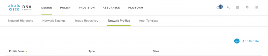
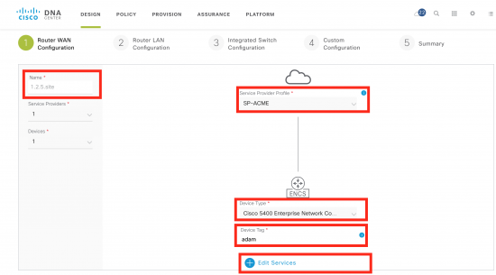
Select the type as “Routing & NFV”. The first step will be to choose the type of device and the WAN connections. Service Provider Profile is defined under Design -> Network Settings -> SP Profiles.
You will also need to configure the WAN connection from the device to the WAN cloud.
Finish by editing the services.
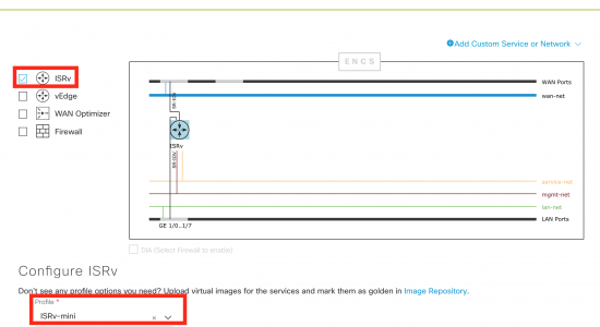
Editing services is where you add the VNF (ISRv) and configure the internal networking. Make sure you have uploaded an ISRv image into the image repository first, so you can chose the VNF profile for the ISRv.
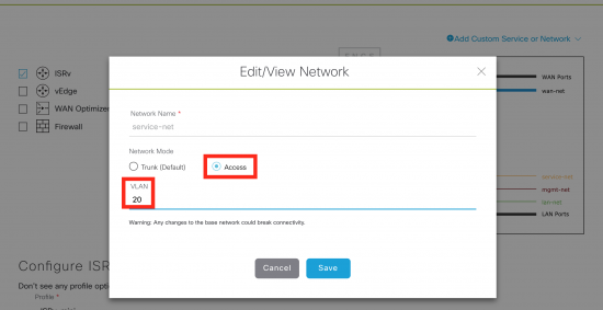
Next step is to click on the service-net and the mgmt-net and add a vlan tag, as well as make it an access network.
In my case, service-net = vlan 20 and mgmt-net = vlan 10
Step two is to configure the connection between the ISR and the switch. In this case it is L3. The protocol is OSPF and the number is 100.
Third step is to configure the VLAN on the switch. In this case, both vlan 10 and 20 are used.
Finally, review the summary and save.
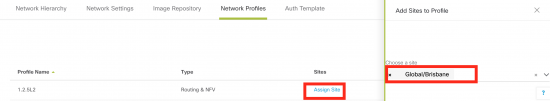
The only thing required to do is to add a site to the profile.
Validation
Once the desing and deployment is completed, the design can be verified by connecting to the 9300 router. The OSPF peering has been established between the 9300 and the ISRv.
encs-9k#show ip ospf ne

Neighbor ID     Pri   State           Dead Time   Address         Interface
192.168.202.17    1   FULL/DR         00:00:36    192.168.200.16  Vlan1
The 9300 and ISR are connected over an L2 link with the peering point on an SVI – vlan 1. It is very simple to change g1/0/1 to a routed interface, or to run an etherchanel underneath, depending on requirements.
encs-9k#show ip int br | inc up
Vlan1                  192.168.200.3   YES DHCP   up                    up
GigabitEthernet0/0     192.168.200.183 YES DHCP   up                    up
GigabitEthernet1/0/1   unassigned      YES unset  up                    up
Loopback0              1.1.1.1         YES TFTP   up                    up
Conclusion
This blog shows the automated deployment of physical and virtual network devices in a branch. Automation is used to deploy the network functions (ISRv router) on an ENCS 5400 and Plug and Play is used to configure the 9300 switch. Other models could also be used.
You can learn more about Plug and Play on my blog site.
We’d love to hear what you think. Ask a question or leave a comment below.
And stay connected with Cisco DevNet on social!
Twitter @CiscoDevNet | Facebook | LinkedIn
Visit the new Developer Video Channel