
Open Radio Access Networks (O-RAN) is transforming the telecommunication industry. It changes traditional appliance-based RAN deployment to more open, interoperable, standard-based and virtualized radio access network. O-RAN deployments remove vendor lock-in and enable telecom service providers to take advantage of virtualization, utilize telecom edge for innovative apps and services, and save costs.
The Cisco Nexus 93180YC-FX3 platform is a popular Data Center switch for O-RAN deployment at Telco Far Edge locations because of its support of the PTP telecom profile (G.8275.1), Sync-e, DC virtualization features, and line rates of 1G, 10G, 25G and 100G interfaces. Organizations can manage and operate these switches consistently across all locations using Cisco Application Centric Infrastructure (ACI) or Cisco Data Center Network Manager (DCNM). The PTP telecom profile and Sync-e are supported in NX-OS 9.3(5) and ACI 5.2.(1) releases.
This blog post explains Open-RAN architecture, the PTP telecom profile, and deployment models of O-RAN with the Cisco Nexus 9000. You will learn how customers are deploying N9K-C93180YC-FX3 for O-RAN in the far edge DCs and building clocking synchronization in the network using PTP telecom profile capabilities supported on this platform.
O-RAN Architecture
The O-RAN architecture is defined by the O-RAN alliance, a worldwide association of mobile network operators, manufacturers, research groups, and academic institutions operating in the Radio Access Network (RAN) industry.
Figure 1 shows the transition from a traditional appliance-based architecture to an O-RAN architecture. The traditional RAN is decomposed into multiple network functions such as O-RU (Open Radio-Unit), O-DU (Open Distributed Unit), O-CU-CP (Open Central Unit Control Plane), and O-CU-DP (Open Central Unit Data Plane). Network functions are deployed on an open computing platform referred to as Open-cloud. Communication between the network functions is over well-defined interfaces, enabling a multi-vendor approach for the RAN.
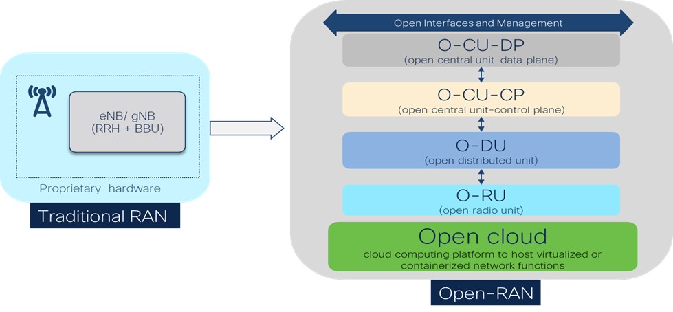
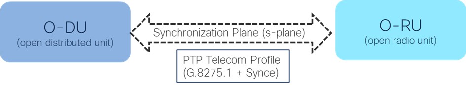
Real time network functions (O-RU and O-DU) are sensitive to timing and latency. They also require high accuracy clock synchronization. O-RAN defines an S-Plane (Synchronization Plane) between O-RU and O-DU to describe a time and frequency synchronization standard through the physical network using Precision Time Protocol (PTP) and Synchronous Ethernet (SyncE).
PTP Telecom Profile
The ITU-T (Telecommunication standardization sector of International Telecommunication Union) defines PTP profiles that allow organizations to specify specific selections of attribute values. In addition, optional features of PTP interwork to achieve performance that meets the requirements of applications when using the same transport protocol.
Two PTP profiles have been defined for the use of PTP in telecom – G.8275.1 (PTP with full timing support from the network) and G.8275.2 (PTP with partial timing support from the network). The purpose of the G.8275.1 profile is to provide the highest accuracy. This requires the implementation of an IEEE 1588 telecom boundary clock or telecom transparent clock in every node in the timing distribution network.
As per the ORAN-standard, devices should utilize the ITU-T G.8275.1 PTP profile for full On-Path Timing Support for O-RAN deployment. This means they should have the relevant timing capabilities and performance such as PRTC Primary Reference Time Clock, T-GM (Telecom grandmaster), T-BC (Telecom Boundary Clock), T-TC (Telecom time slave clock), etc.
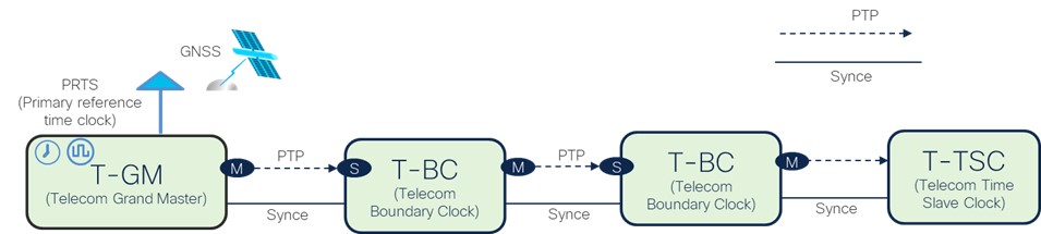
Figure 3 illustrates the PTP telecom profile G.8275.1. The T-GM is connected to a PRTS (Primary Reference Time Clock) such as a GNSS (Global Navigation Satellite System) receiver. The T-GM can also be a GNSS receiver and act as a PRTS. It sends time to downstream T-TSC or T-BC using PTP packets.
The T-BC recovers time from PTP packets received on the PTP slave port from the T-GM or another T-BC. It then synchronizes its clock from recovered time, then generates and sends PTP packets over its master port to a T-BC or T-TSC. The T-BC actively participates in PTP and plays an important role in maintaining clock accuracy. The Cisco N9K-C93180YC-FX3 switch supports the T-BC role of the PTP G.8275.1 profile.
T-TSC refers to a device consisting of a slave-only ordinary clock (OC) that receives the time from the upstream T-BC or T-GM using PTP packets. O-RU and O-DU use T-TSC functionality to receive the clock.
The telecom profile mandates the use of SyncE along with PTP for the best performance. This is called PTP hybrid mode. The Cisco N9K-C93180YC-FX3 supports PTP hybrid mode, where frequency synchronization is done through SyncE, while time and phase synchronization are done using PTP.
For frequency synchronization, SyncE leverages the Ethernet physical layer to transmit the frequency to remote sites. SyncE’s functionality and accuracy resemble the SONET/SDH network because of its physical layer characteristics. SyncE uses the Ethernet Synchronization Message Channel (ESMC) to carry a Quality Level (QL) identifier that provides the timing quality. Information provided by QLs during network transmission helps nodes derive timing from the most reliable source and prevents timing loops.
Clock Synchronization (S-Plane) between O-RU and O-DU
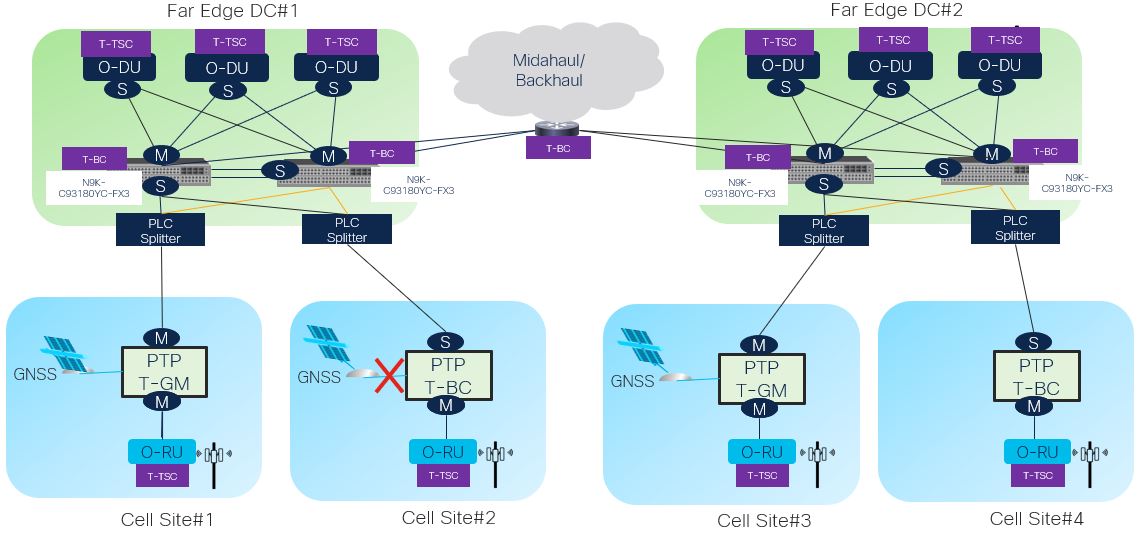
Figure 4 shows an O-RAN topology enabled by the support of PTP telecom profile G.8275.1 and SyncE on the Cisco N9K-C93180YC-FX3 switch. There could be several other topologies, depending upon physical sites, GNSS connectivity, and placement of O-RU/O-DU.
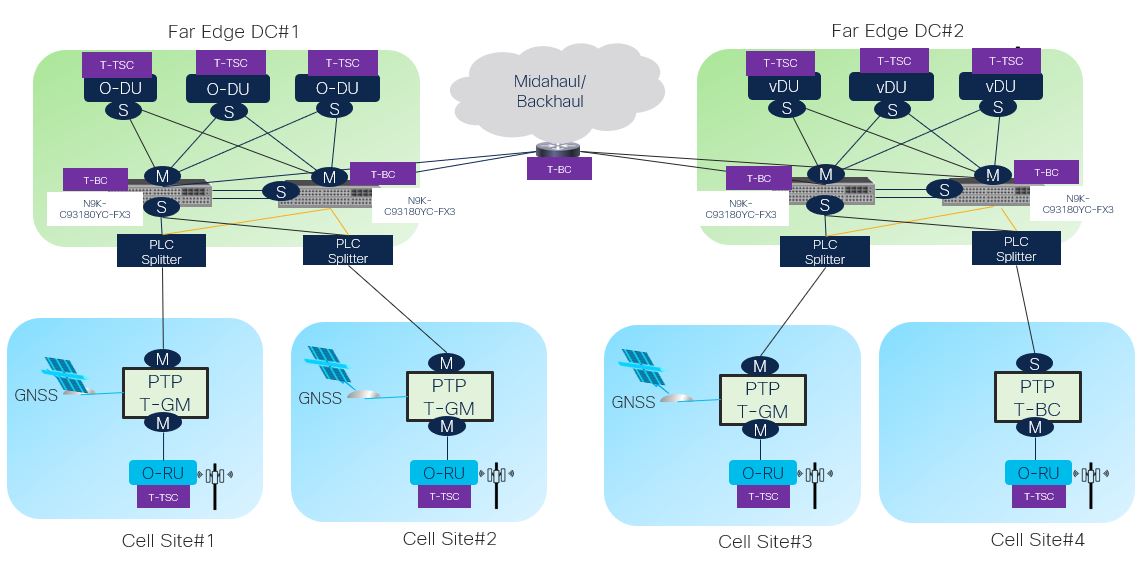
In the above topology, Cell Site#1 and Cell Site#2 are connected to Far Edge DC#1. The PTP T-GM at these cell sites receives its clock from a local GNSS. O-RUs at these cell sites synchronizes their clocks directly with a PTP T-GM. O-DUs for these cell sites are centrally located in Far Edge DC#1. These O-DUs receive their clock from the Cisco N9K-C93180YC-FX3 through the network using its T-BC functionality.
Cell Site #4 doesn’t have a local GNSS, and O-RUs at this site receive their clock from the Cisco N9K-C93180YC-FX3 acting as a T-BC in the Far Edge DC#2.
Let’s consider a few clock failure scenarios.
If the PTP T-GM at Cell Site#2 doesn’t receive its clock from a local GNSS, it will change itself from a T-GM to a T-BC. Then it will receive its clock from the Cisco N9K-C93180YC-FX3 located in Far Edge DC#1 and deliver the clock to the O-RUs as shown in Figure 5.
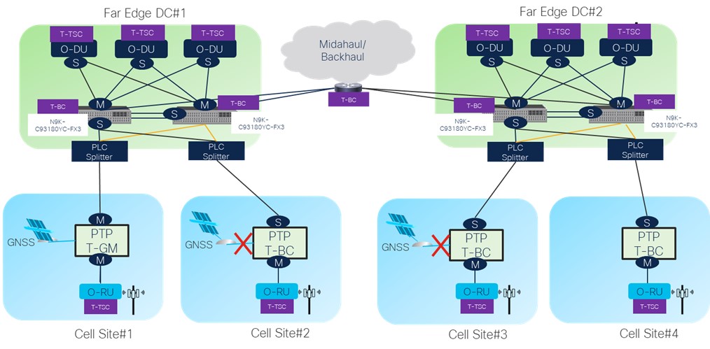
Another failure scenario could be a GNSS connectivity failure at both Cell Site#2 and Cell Site#3. In this case, clocks to O-RUs connected to Cell Site#3 and #4, as well as O-DUs connected to Far Edge DC#2, can be delivered from the PTP T-GM of Cell Site#1. These are sent through the network using the T-BC capabilities of the Cisco N9K-C93180YC-FX3 at the Far Edge DC and the midhaul/backhaul router as shown in Figure6.
Organizations are deploying the Cisco Nexus 9000 in Far Edge DCs for O-RAN deployment to take advantage of its DC feature richness and support of critical timing features such as the PTP G.8275.1 telecom profile, and SyncE.
O-RAN deployments based on the Nexus 9000 eliminate vendor lock in and enable telecom service providers to take advantage of virtualization, utilize telecom edge for innovative apps and services, and save costs.
References
To understand more about O-RAN, the PTP telecom profile, and implementation of PTP, refer to following reference documents.
- Cisco Nexus 93180YC-FX3 platform
- O-RAN Alliance
- PTP telecom profile (G.8275.1) for phase/time synchronization with full timing support from the network
- Timing characteristics of telecom boundary clocks and telecom time slave clocks
- PTP telecom profile and synce support on Nexus 9000
- PTP telecom profile support on ACI
- Synce support on ACI
- Cisco ACI
- Cisco Nexus 9000


