
I did not sleep well last night. My rest was disturbed by oneiric memories of old situations where I wasted multiple hours in a queue, locked in my car under the sun and without an option to reach the nearby exit. Unpleasant feelings, I have to admit. Maybe not so different from what happens to storage network administrators when application users complain of poor performance and have the habit to finger point the network team. On highways or storage networks, congestion is never nice.
FC SANs – Background
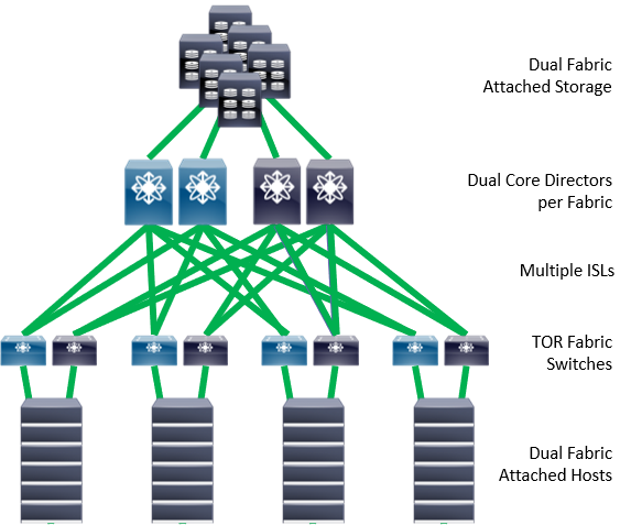
Today’s Fibre Channel Storage Area Networks are very high speed, very reliable networks that can connect 1000s of different end devices. These end devices are primarily comprised of servers, called ‘initiators’, and storage arrays, called ‘targets’. These devices are not dedicated to each other and do not have dedicated connections in the SAN itself, but often communicate to many different devices across a shared Inter Switch Links (ISLs) infrastructure. Additionally, the ‘initiator’ devices are in communication with multiple ‘targets’ storage arrays and the ‘target’ storage arrays are in communication with multiple ‘initiator’ devices.
These networks are considered ‘lossless’ because frames are not discarded or dropped, unless very specific error conditions are encountered. The end devices issuing SCSI or NVMe IO operations rely on this ‘no drop’ capability and only perform well under those conditions. Actually, the traffic patterns specific to storage needs, the ‘no drop’ promise and the fabric-wide services embedded in Fibre Channel switches are all hinted at when we describe this as a storage fabric and not a generic network.
Because of the ‘no drop’ capability of these networks, the shared ISLs infrastructure as well as the shared use of initiators and targets, there can be widespread congestion problems when devices are exhibiting certain negative behaviors. These congestion problems can affect large numbers of end devices, even devices that are not in direct communication with each other because part of different zones.
Congestion in rough terms
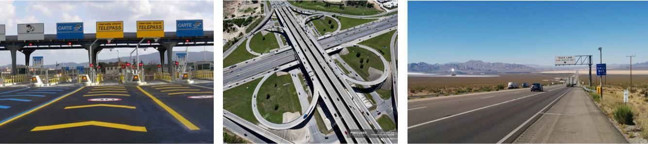
To understand how these end devices can cause congestion, consider a highway system similar to what is found in the US, Europe or elsewhere. These highway systems are comprised of four basic components:
1 – Entrances/Exits/Interchanges – This is where traffic enters and exits the system (at times with a ticket or toll booth) or changes the route (North-South direction to East-West direction). Interchanges use grade separation to avoid interruption from other crossing traffic streams and differ from intersections, where traffic may get halted to give precedence to others.
2 – Highways between the interchanges – These are comprised of various numbers of lanes, distances and relevant speed limits.
3 – End destinations – These are like homes, stores, hospitals, gas stations, etc.
4 – Vehicles – These are the entities making use of the highway system.
In this analogy, Entrances and Exits are like Fibre Channel switch ports that allow traffic from end nodes to get in and out of the SAN. Interchanges are like the switches when connecting to other switches. Highways between interchanges are like ISLs. End destinations are like the ‘initiators’ and ‘targets’ and they either receive or transmit the vehicular traffic. Vehicles are like the Fibre Channel frames and are the actual traffic transported by the SAN ‘system’.
In a similar way, the highway system is ‘lossless’ in that all vehicles entering the system will also exit the system at some point (well, I know, sad exceptions happen). Also, the highway system is designed with a given capacity as measured in speeds and vehicles per hour. The capacity of various Entrances/Exits/Interchanges will vary as well as the capacity of different sections of the highways themselves will vary. For example, one Entrance/Exit/Interchange might be designed with multiple free flowing lanes to allow a much greater capacity than a little used Entrance/Exit/Interchange with a simple stop sign.
Flow Control
Underlying all of this is flow control. Flow control exists in all types of networks to equalize the input and the output. Flow control in highway networks consists of vehicle to vehicle spacing, stop signs, speed limits, traffic lights, etc. Some places where congestion is prevalent, like California, even have ingress pacing lights which can control the rate of vehicles entering the highway. This can be considered a simple honor-based ingress rate limiting solution. Fibre Channel SANs have their own flow control mechanism. This is on each link and utilizes ‘Buffer to Buffer Credits’. In this mechanism each side of the link can directly control the amount of data the other side can send to it.
Finally, the data that is transported by the Fibre Channel SAN is made up primarily of Read and Write IO operations. Read commands are issued by initiators and solicit (request) a specific target to send it an amount of data. Write commands ultimately send data from an initiator to a target but not before the target end solicits (requests) the data from the initiator.
Compare this to the shopping center mailer advertisements as solicitations for vehicles. In Fibre Channel, both initiators and targets solicit data. Initiators do this via SCSI/NVMe Read commands. Targets solicit data, after receiving a SCSI/NVMe Write command, via the Transfer Ready requests. Both the Read command and the Transfer Ready request can solicit large or small amounts of data.
You have reached the end of Part 1 of my blog. In Part 2 I will keep focusing on this same topic and provide some scenarios. Keep reading.


Crystal Clear!