
This is the second of a two-part blog series developed in association with Tom Edsall, a Cisco Fellow and CTO of Insieme Networks, recently acquired by Cisco Systems. While Part 1 focused on the role of SDN overlays and deployment considerations, this one delves into the benefits derived from such a model in an ACI implementation.
First, an insight into these design principles and the focus on applications from some of the top Insieme engineers-
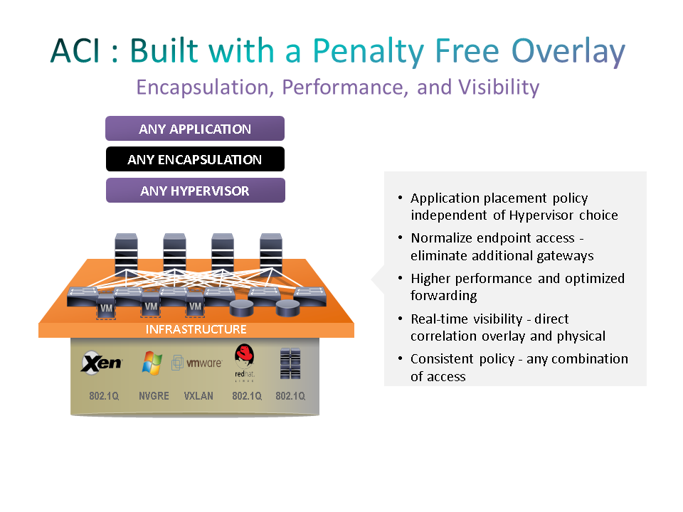
Benefits of Overlay Integration in ACI deployments
If you have a small amount of state to update when an application moves or is added to the data center you will scale better than if you have a lot of state to update. With the ACI implementation, we are pretty fortunate in that the amount of state required by the mapping database is relatively small. It is a simple binding of identity to location. There is other state not related to the overlay such as access policy which may be larger, but that will be discussed at another time as it is not strictly required for the overlay. The amount of state that changes for a single move does not change with the size of the data center.
Reliability is also an obvious factor. If you cannot reliably communicate, then steps must be taken to address that reliability. The less reliable the communication is, the more burdensome it will be to compensate and make it reliable. Again, in the data center, communication is fairly reliable and simply using TCP is probably good enough. In our ACI system we use TCP to propagate state, however we have the additional guarantee that we use application data itself to trigger the state propagation if it were to initially fail. This helps make the system extremely robust.
The number of places you have update state is clearly a big factor. In many solutions, the number of places you have to update state is equal to the number of servers in the data center, which is huge. It also implies that it increases with the size of the data center. We found this to be greatest factor influencing scale and consequently reliability. Our unique ACI solution must update only a very small, and constant, number of locations in order to guarantee proper network behavior. By small, we mean less than 14 and only 6 for most data center designs, i.e. it scales order one – O(1). This is a fantastic scaling property because it is invariant with the size of the data center and it makes the previous mentioned concerns, frequency, amount, and reliability, much less of a concern. If I only have to propagate state changes to 6 places, I can afford to do it more often, with more state, and take whatever measures are necessary to make it reliable.
We achieve this remarkable scaling property by using a combination of data path learning, caching, and exploiting the last consideration – consistency. We have relaxed the consistency requirements by having the network correct out of date mapping decisions on the fly as the packet flows through the network. This technique will guarantee packet delivery even when only a small number of switches have been updated. Furthermore, we learn from the data path to correct the remaining instances of the mapping database using a caching mechanism driven by the data path application data. The cache entries are either aged out or are updated by the flow of application data. On top of all this, we update the mapping database at line rate without any latency impact on the first packet or any other packet. It is essentially “penalty” free, i.e. there is no impact on application performance due to the overlay, making it a fairly unique offering in the market today.
Centralized Controller -Scalable and Reliable
One of the additional benefits of doing the overlay in this manner is that the centralized controller is not involved in the overlay or the mapping database. This means that this controller is not a single point of failure for the entire network nor is it a factor in how well the overlay scales. Other solutions in the market are dependent on a centralized controller for their overlay mapping and therefore have to create a centralized controller that must scale with the size of the data center and must be incredibly, (one may contend impossibly) reliable. The high reliability requirement is because a failure of their controller essentially takes out the entire datacenter. Our approach is to remove the controller from the critical path such that a controller failure is a maintenance event rather than a catastrophe .
The specific overlay packet format we use is generally not very important to the network administrator. For those that care about the details, we use VxLAN. We chose VxLAN because it is standards based, is widely supported in both custom and merchant silicon, works over any network that can transport IP packets, and supports both layer 2 and layer 3 semantics. An alternative choice would have been NvGRE that meets these same objectives. However, NvGRE encapsulated traffic is not load balanced properly by a lot of existing networking equipment. So, all else being equal, we chose VxLAN. However, we do support the translation or gateway function between NvGRE and our internal VxLAN in all of our edge devices so there is no constraint in using NvGRE in devices attached to the network.
An additional benefit of our overlay implementation is that it not only provides the ultimate in flexibility for application placement and movement, it also provides a nearly unlimited number of virtual networks. Traditional networks have supported virtualization through the use of VLANs and VRFs. VLANs giving you layer 2 virtualization and VRFs giving you layer 3 virtualization. However, these solutions are severely limited. The VLAN field in the packet is 12 bits giving you 4K VLANs and must be unique across the network. VRFs consume a lot of router CPU cycles and are often limited to small numbers, on the order of a 1000 as well. With our VxLAN overlay, there is a virtual network identifier in the packet that is 24 bits potentially giving us 16 million virtual networks. We use this field to identify both layer 2 domains and layer 3 domains depending on whether the packet is bridged or routed. This allows us to support 10s of thousands of these L2 and L3 domains. These are generally testing or software limits rather than hardware limits and will likely increase over time if the market demands it. This translates into a solution that can support 10s of thousands of tenants each with their own set of layer 2 domains and dedicated address spaces.
The final result of our overlay implementation is that we have a solution that –
- Separates location from identity providing the necessary flexibility in the data center network.
- Scales independent of network size, O(1).
- Does not introduce a ‘single-point-of-failure controller’ into the system.
- Works the same for both virtualized and non-virtualized workloads.
- Does not consume any additional CPU cycles from the compute infrastructure for network operations.
- Scales the number of logical networks beyond current commercial needs.
This concludes our two-part blog series. We welcome your feedback and comments. For more information on Cisco’s approach to Application Centric Infrastructure, please visit www.cisco.com/go/aci.


좋네..
Great article! Love learning more about the role of software and networking.
Hello,
VxLAN doesn’t provides separation of location and identity. All these functionality implemented in LISP.