
Over the last 12 months I’ve been doing a lot of work that has involved the Cisco Nexus 1000v, and during this time I came to realise that there wasn’t a huge amount of recent information available online about it.
Because of this I’m going to put together a short post covering what the 1000v is, and a few points around it’s deployment.
What is the Nexus 1000v?
The blurb on the VMware website defines the 1000v as “..a software switch implementation that provides an extensible architectural platform for virtual machines and cloud networking.”, and the Cisco website says, “This switch: Extends the network edge to the hypervisor and virtual machines, is built to scale for cloud networks, forms the foundation of virtual network overlays for the Cisco Open Network Environment and Software Defined Networking (SDN)”
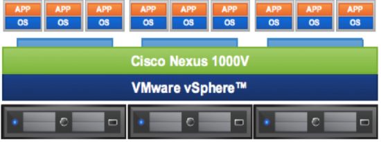
So that’s all fine and good, but what does this mean for us? Well, the 1000v is a software only switch that sits inside the ESXi (and KVM or Hyper-V, if they’re your poison) Hypervisor that leverages VMware’s built-in Distributed vSwitch functionality.
It utilizes the same NX-OS codebase and CLI as any of the hardware Nexus switches, so if you’re familiar with the Nexus 5k, you can manage a 1000v easily enough, too.
This offers some compelling features over the normal dvSwitch such as LACP link aggregation, QoS, Traffic Shaping, vPath, and Enhanced VXLAN, and would also allow an administrative boundary between servers and networking, even down to the VM level. Obviously all the bonuses of a standard dvSwitch around centralised management also still apply.
Components of the 1000v
The 1000v is made up of 2 main components, 2 VSMs, and the VEMs. The VSMs are the Virtual Supervisor Modules, which equate to a supervisor module in a physical multi-chassis switch, and the VEMs are like the I/O blades that provide access to the network.
Virtual Supervisor Modules
The VSM runs as a VM within the cluster, with a second VSM running as standby on another ESXi host. Good practice would be to set an affinity rule to prevent both VSMs living on the same host in case of host failure.
Virtual Ethernet Modules
The VEM is the software module that embeds in the ESXi kernel and ties the server into the 1000v.
1000v Deployment
There are 2 ways of deploying the 1000v, Layer 2 mode (which is deprecated) and Layer 3 mode which allows the VSMs to sit on a different subnet to the ESXi hosts.
Deploying the 1000v is relatively straight forward, and this post is not designed to be a step-by-step guide to installing the 1000v (Cisco’s documentation can be found here). The later versions of the 1000v have a GUI installer which makes initial deployment simple.
Once the VSM pair has been deployed you need to:
Create a L3 SVS (SVS config sets how the VEMs connect to the VSMs) domain, and define your L3 control interface
- 1000v# svs-domain
- 1000v(config-svs-domain)# domain id 10
- 1000v(config-svs-domain)# no packet vlan
- 1000v(config-svs-domain)# no control vlan
- 1000v(config-svs-domain)# svs mode L3 interface mgmt0
Create a SVS connection to link the VSM with vCentre
- 1000v# svs connection vcenter
- 1000v(config-svs-conn)# protocol vmware-vim
- 1000v(config-svs-conn)# remote ip address 192.168.1.50
- 1000v(config-svs-conn)# vmware dvs datacenter-name London
- 1000v(config-svs-conn)# connect
Create your Ethernet (physical uplink port-profiles) and vethernet (VM port-profiles) port-profiles, and add L3 capability to your ESXi management vmk port-profile
- 1000v# port-profile type veth esxi-mgmt
- 1000v(config-port-prof)# capability l3control
- Warning: Port-profile ‘esxi-mgmt’ is configured with ‘capability l3control’. Also configure the corresponding access vlan as a system vlan in:
- * Port-profile ‘esxi-mgmt’.
- * Uplink port-profiles that are configured to carry the vlan
- 1000v(config-port-prof)# vmware port-group
- 1000v(config-port-prof)# switchport mode access
- 1000v(config-port-prof)# switchport access vlan 5
- 1000v(config-port-prof)# no shut
- 1000v(config-port-prof)# system vlan 5
- 1000v(config-port-prof)# state enabled
- 1000v(config-port-prof)# port-profile type ethernet InfrUplink_DvS
- 1000v(config-port-prof)# vmware port-group
- 1000v(config-port-prof)# switchport mode trunk
- 1000v(config-port-prof)# switchport trunk allow vlan 5
- 1000v(config-port-prof)# channel-group auto
- 1000v(config-port-prof)# no shut
- 1000v(config-port-prof)# system vlan 5
- 1000v(config-port-prof)# state enabled
Note the point above where you have to put a “system vlan” on your l3control interface, this ensures network traffic on that VLAN will always remain in the forwarding state, even before a VEM is programmed by the VSM, especially important in the case of the control interface.
Deploy the VEMs to the ESXi hosts (this can be done from the GUI)
Once the VEMs are on the ESXi hosts, you need to migrate the ESXi management vmk into the 1000v, this will then show the VEMs and the ESXi hosts in the 1000v when you run the ‘show modules’ command.
At this point we have communication between the VSM and the VEMs within ESXi, and we can start configuring port-profiles for our non-management traffic.
Simple, right?


Thank you so much, Ed 🙂 Yes, it’s very simple after reading the article 🙂