
A Comparative Analysis of Architectures and Their Trade-offs
Organizations have many options when implementing an Ethernet Virtual Private Network (EVPN). Choice of network design with respect to overlay routing may be influenced by a combination of factors, including scalability, multi-tenancy, segmentation, and operational simplicity. Understanding the key differences among various overlay routing architectures makes it possible to evaluate and choose an implementation that offers a best fit for an organization.
This blog post compares the trade-offs across different overlay Anycast routing architectures in the context of overlay networks deployed using EVPN Integrated Routing and Bridging. It covers Centralized Routing, Distributed Asymmetric Routing, and Distributed Symmetric Routing. Note that this discussion is independent of data plane encapsulation and applies equally to IP and MPLS tunnel data paths.
Overlay Networks
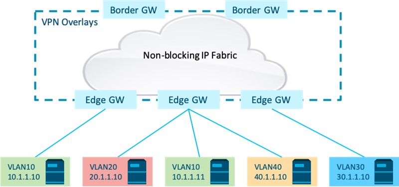
Overlay networks have become ubiquitous across enterprise, data center, and service provider network architectures. They enable deployment of a simple non-blocking IP routed infrastructure with the flexibility to deploy multi-tenant unicast and multicast services on top. Overlay endpoints or workloads may be placed or moved anywhere across a non-blocking fabric, independent of overlay addressing and subnet assignments. A flexible and scalable IP Clos fabric provides reachability across edge and border devices. A VPN tunnel mesh across edge and border devices provides overlay connectivity between connected endpoints (see Figure 1).
There may be additional factors, including security and traffic engineering policies, to consider when deploying an overlay across different use cases. Reachability, however, is the least common denominator across all overlay use cases. For flexible workload placement and mobility that is independent of addressing and subnetting constraints, a multi-tenant overlay network must provide reachability across:
- Tenant endpoints within an IP subnet,
- Tenant endpoints in different IP subnets.
As intra-subnet overlay connectivity is enabled via layer 2 VPN bridging services deployed across fabric edge and optionally border devices, multiple options exist for overlay routed connectivity between endpoints in different subnets. The following will detail and compare trade-offs across three overlay Anycast routing architectures:
- Centralized Routing
- Distributed Asymmetric Routing
- Distributed Symmetric Routing
1 – Centralized Anycast Routing Architecture
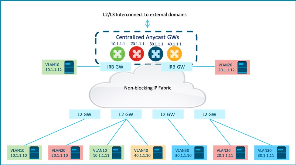
A centralized routing model connects endpoints to layer-2 EVPN gateways (GW) that provide VPN bridging. This enables intra-subnet flows across the overlay while all routing to endpoints in different subnets, within and outside the fabric, is centralized via designated Integrated Routing and Bridging (IRB) L2+L3 GWs.
First-hop routing for each overlay subnet is deployed using a subnet Anycast GW that is hosted on one or more designated IRB GW nodes. A key attribute defining this overlay routing architecture is that first-hop routing function for an overlay subnet is decoupled from the EVPN L2-GW edge that provides intra-subnet bridging service for that subnet. This decoupling results in first-hop routing for overlay endpoints across the fabric being “centralized” on designated IRB nodes. Note that the Anycast GW for each subnet is still distributed across these “centralized” IRB GW nodes.
It is common to deploy first-hop Anycast routing for all overlay subnets in a fabric on the same set of IRB nodes. While not necessarily required, this is often done for operational simplicity and optimal routing. It is also common for this first-hop routing function to be hosted on border nodes that also act as interconnect GWs to external L2 or L2/L3 domains. Optionally, these IRB nodes may also function as edge nodes and connect to local overlay endpoints, resulting in the model shown in Figure 2.
Control Plane Operation
A centralized approach essentially uses an EVPN overlay as a layer-2 VPN overlay, with the inclusion of the host IP along with the host MAC being optional in EVPN host route advertisements (see Figure 3). The host route is advertised by the egress L2 GW with layer 2 attributes that, on the ingress L2 GW and on the centralized IRB GW, result in:
- Import of the host MAC to the MAC VRF in the control plane.
- Host MAC reachability via layer-2 VPN encapsulation and tunnel to the egress GW.
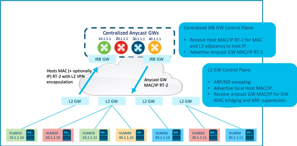
In addition, IRB GW nodes also install layer-3 adjacencies to the remote host IP. Host IP to MAC bindings for this purpose may be learnt on the IRB GW via:
- Advertising L2 GW learning the host IP by snooping and including the host IP in the EVPN host route advertisement.
- OR in data plane via ARP and ND packets received from the host.
Note that reachability to a remote layer-3 host adjacency is still resolved by host MAC reachability via a layer-2 VPN tunnel to the egress GW. In addition, IRB gateways may also proactively advertise the Anycast GW MAC/IP in the EVPN control plane for the purpose of avoiding duplicate ARP responses from redundant Anycast GWs. On the L2 GW, this results in L2 reachability to Anycast GW MACs in the MAC VRF, and local ARP suppression for Anycast GW IP ARP requests from hosts.
Data Plane Operation
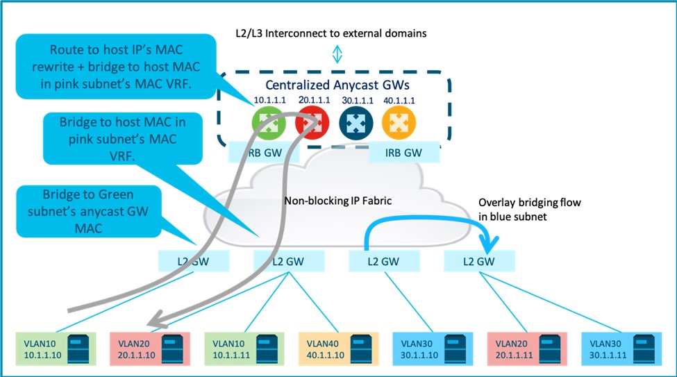
For data plane operation (see Figure 4), intra-subnet flow destined to a remote host is bridged on the ingress L2 GW via a tunnel to the egress L2 GW, with the layer 2 VPN encapsulation advertised by the egress L2 GW. On the egress L2 GW, this layer 2 VPN encapsulation maps to a MAC VRF, where the packet is again bridged to the local host.
Inter-subnet flow destined to Anycast GW MAC is bridged on the ingress L2 GW to one of the centralized IRB GW via tunnel to the IRB GW with layer 2 VPN encapsulation advertised by the IRB GW. Packets are then routed on the IRB GW via layer-3 adjacency to the destination host IP. This results in the packet being encapsulated with the host MAC rewrite that resolves via tunnel to the egress L2 GW and layer 2 VPN encapsulation advertised by the egress L2 GW. On the egress GW, this layer 2 VPN encapsulation maps to the MAC VRF, where the packet is again bridged to the local host.
Control Plane Scalability – Limited by “all subnets on centralized GWs”
Control plane scalability is limited by the fact that each IRB node that is part of the centralized Anycast GW cluster is required to program:
- Layer-3 (SVI) interfaces for ALL overlay subnets for which it is a first-hop GW.
- Layer-3 adjacencies to ALL overlay endpoints in these subnets.
- MAC VRFs for ALL overlay subnets for which it is a first-hop GW.
- MAC routes for ALL overlay endpoints in these subnets.
- IP host routes for ALL overlay endpoints across the fabric.
- Overlay tunnels to ALL edge nodes.
A simple deployment centralizes all overlay subnets on the same set of IRB nodes. In this case, the fabric wide scale of overlay subnets and endpoints is limited by the IRB device’s individual layer 3 interface, layer adjacency, and MAC route scale. Note that in this model, redundant nodes that are part of the same Anycast GW cluster do not contribute to overall fabric scale, since the same forwarding state needs to be replicated across all Anycast GW nodes.
Control Plane Scalability – At the cost of optimal routing
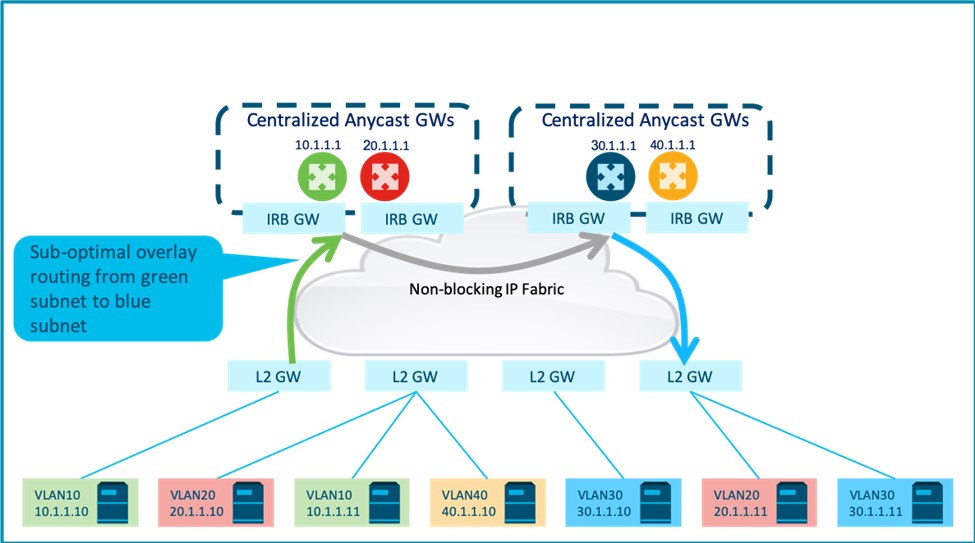
Alternatively, first-hop routing service for different subnets may be load-shared across multiple centralized Anycast GW clusters to reduce the scale on each IRB node.
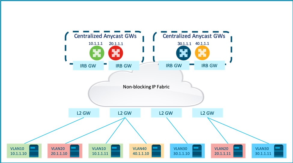
Figure 5 shows first-hop routing for two subnets hosted on the first two IRB nodes with routing for two other subnets hosted on the other two IRB nodes. However, this may result in a sub-optimal data path with an extra routing hop as shown in Figure 6. It also compromises the operational simplicity of being able to manage routing for all overlay subnets on the same IRB nodes.
Sub-optimal Data Path – Local inter-subnet flows
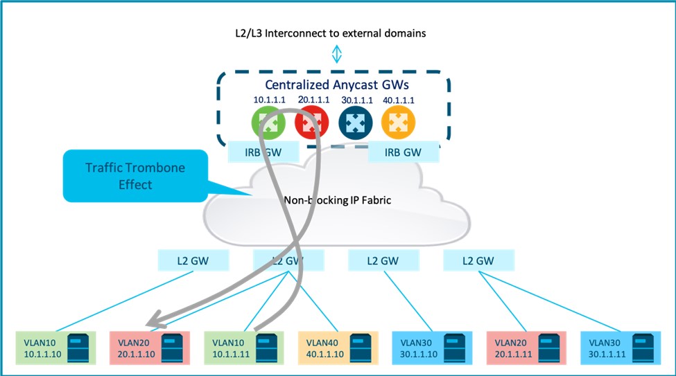
The sub-optimal nature of inter-subnet routing in this approach applies to local inter-subnet flows that must always be bridged on the ingress L2 GW to the centralized IRB GW, only to be routed back to the ingress L2 GW. This results in a ‘traffic trombone effect’ (see Figure 7).
Operational Simplicity
Despite these sub-optimal scaling and data path properties, this approach is still a good trade-off in certain use cases for operational reasons:
- This approach provides operational simplicity of provisioning and managing first-hop routing and associated routing policies for all overlay subnets on designated nodes. As an example, for use cases where an overlay subnet is stretched across campus and DC domains, this approach allows you to manage inter-subnet and external routing policies for the subnet at a central point.
- Forwarding semantics, being similar to traditional IRB, are simple to understand, deploy, and operate.
- EVPN centralized routing design, in principle, aligns with legacy access/distribution layer-2 network design, where routing functionality is centralized and decoupled from layer-2 only access devices. An EVPN layer 2 overlay can be thought of as replacing a traditional layer-2 access network, with EVPN-IRB functionality on centralized distribution nodes being the traditional L2/L3 boundary. It is hence a conceptually easier transition from such legacy architectures.
Centralized Anycast GW Redundancy – just FYI
The Centralized Anycast GW approach across redundant IRB GWs introduces additional complexity that an operator should be aware of:
- If L2 GWs only advertise host MAC routes in the EVPN control plane, host layer-3 adjacencies are learnt on the Anycast GW via ARP and ND. Since adjacencies could be learnt on any of the redundant GWs, Anycast GWs must implement additional mechanisms to sync layer-3 host adjacencies across them. Alternatively, L2 GWs must implement MAC-IP learning via snooping and advertise the host MAC and IP via the EVPN control plane for Anycast GW nodes to learn host layer-3 adjacencies via EVPN.
- ARP requests for an Anycast GW IP from a host is flooded across the overlay and hence results in multiple ARP responses from redundant GWs. To avoid this, Anycast GWs must advertise the GW MAC-IP bindings upfront via the EVPN and L2 GWs must implement local ARP suppression. In the case of a VXLAN fabric, Anycast VTEP may also be used across redundant GWs to avoid multiple ARP responses.
2 – Distributed Asymmetric Routing Architecture
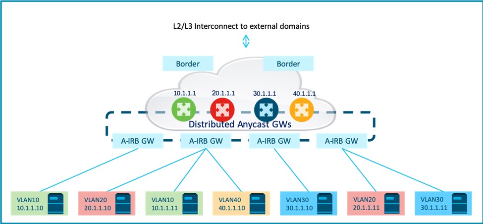
The distributed asymmetric approach is a variation of the centralized Anycast routing approach, with the layer 2/3 routing boundary pushed to fabric leaf nodes (see Figure 8). In this approach, first-hop Anycast GW functionality for an overlay subnet is deployed across ALL leaf nodes that now operate as IRB GWs (as opposed to being L2 GWs).
Control Plane Operation
Much like the centralized IRB approach, this approach also uses the EVPN overlay as a layer-2 VPN overlay. A slight difference is that the host IP is now required in the EVPN host route advertisement, along with the host MAC. Similar to centralized IRB operation, the host route is advertised by the egress GW with layer 2 attributes that, on the ingress GW, results in:
- Import of the host MAC to the MAC VRF in control plane.
- Host MAC reachability via layer-2 VPN encapsulation and tunnel to the egress GW.
IRB-capable nodes also install layer-3 adjacencies to the remote host IP with IP to MAC binding learnt via host routes. Reachability for remote layer-3 host adjacency is still resolved by host MAC reachability via a layer-2 VPN tunnel to the egress GW.
Data Plane Operation
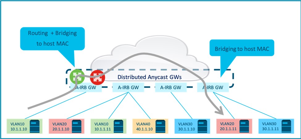
While this approach enables EVPN routing and bridging functions to be co-located on EVPN leaf nodes, it has the same forwarding semantics as a centralized Anycast GW. The overlay routing function on the leaf IRB GW routes packets directly to the host’s layer-3 adjacency. “Asymmetric” in this context refers to the fact that this results in inter-subnet flows being “routed and bridged” on the ingress IRB GW and “bridged” on the egress IRB GW (Figure 9).
Control Plane Scalability – Limited by “all subnets everywhere”
Control plane scalability is even more severely limited by the fact that each IRB leaf node is now required to program:
- Layer-3 (SVI) interfaces for ALL overlay subnets in the IP VRF, even if it does not have locally attached hosts in that subnet.
- Layer-3 adjacencies for ALL overlay endpoints in these subnets, even if it does not have locally attached hosts in that subnet.
- MAC VRFs for ALL overlay subnets in the IP VRF, even if it does not have locally attached hosts in that subnet.
- MAC routes for ALL overlay endpoints in these subnets, even if it does not have locally attached hosts in that subnet.
- IP host routes for ALL overlay endpoints across the fabric in an IP VRF.
As a result, fabric wide scale of overlay subnets and endpoints is limited by each leaf device’s layer 3 interface, layer adjacency scale, and MAC route scale. Adding more GW devices to the Anycast GW cluster does not mitigate this limitation, as ALL leaf nodes host routing interfaces, layer-3 adjacencies, and MAC routes for ALL subnets and endpoints across the IP VRF.
Optimal Data Path – Local routing
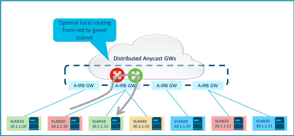
In contrast to centralized IRB, local inter-subnet flows are always routed locally on the ingress GW, while inter-subnet flows across the fabric are always routed directly to the remote host (see Figure 10).
Operational Simplicity – Traditional IRB forwarding
- Much like the centralized IRB approach, this approach also uses the EVPN overlay as a layer-2 overlay (akin to a traditional switching fabric). It treats remote IP endpoints as directly connected layer-3 adjacencies. Forwarding semantics, being similar to traditional IRB, are still simple to understand, deploy, and operate.
- Pushing the first-hop routing function to EVPN leaf GWs is a shift from traditional centralized routing designs. When migrating a legacy switching design, network designers must view EVPN fabric roles for network devices, independent from traditional access / distribution switching roles.
3 – Distributed Symmetric Routing Architecture
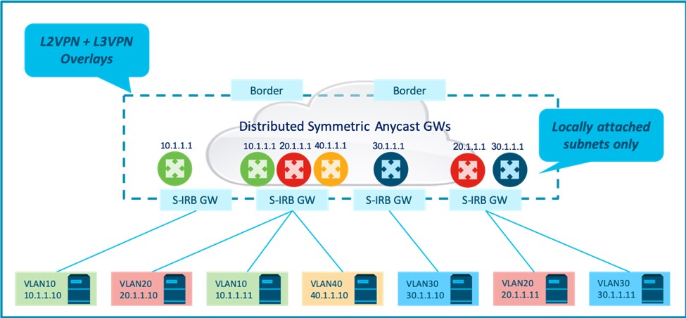
Much like the distributed asymmetric routing architecture, the distributed symmetric approach deploys the first hop Anycast GW function for an overlay subnet across ALL leaf nodes that operate as IRB GWs. However, for better scalability, symmetric IRB forwarding semantics and control plane operation are much different from that of asymmetric or centralized IRB that use EVPN to build a layer-2 VPN overlay. Instead of routing functionality being achieved via traditional IRB over the layer-2 overlay, the symmetric IRB approach uses EVPN as a single control plane to build:
- A layer-2 VPN overlay to enable intra-subnet bridging.
- A layer-3 VPN overlay to enable inter-subnet routing.
This additional layer-3 VPN overlay is the key differentiating attribute of a symmetric IRB architecture. It allows restriction of subnet provisioning on edge devices to locally attached subnets. This results in better scaling properties.
Control Plane Operation
To build an additional layer-3 VPN overlay for inter-subnet routing, EVPN MAC+IP host routes are advertised with additional layer-3 VPN attributes to enable:
- Layer-3 VPN import to IP VRF in the control plane.
- Layer-3 VPN encapsulation in the data plane.
In summary, a single host route in the control plane is used to signal a layer-3 VPN host route to be installed in the IP VRF and a layer-2 VPN MAC route to be installed in MAC VRF, with the corresponding L3VPN and L2VPN encapsulations.
Data Plane Operation
- Intra-subnet bridging – Much like as is the case with the asymmetric and centralized approaches, bridging across the layer-2 VPN overlay is accomplished via layer-2 VPN encapsulation (L2 MPLS label or L2 VNI) that maps to the local MAC VRF. Bridged forwarding plane is identical across all three routing architectures.
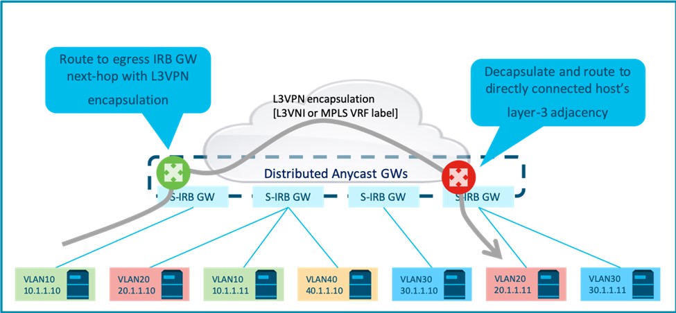
- Inter-subnet routing – Inter-subnet flows are routed on the source (ingress) GW to the destination (egress) GW next-hop via a tunnel to the egress GW with L3VPN encapsulation. This L3VPN encapsulation is terminated and identifies the IP VRF at the egress GW, where the packet is again routed in the IP VRF to a locally connected endpoint. This routing data path is similar to traditional L3VPN, with the EVPN GWs acting as L3VPN PE devices.
Control Plane Scalability – No more “all subnets everywhere”
A separate layer-3 VPN overlay allows inter-subnet host reachability on the source GW to be recursively resolved via a L3VPN tunnel to a destination GW next-hop. This differs from the asymmetric and centralized approaches where the source GW relies on layer-3 adjacencies to all remote hosts and their host MAC reachability via layer-2 VPN tunnels to achieve inter-subnet routing. As a result:
- The ingress GW no longer needs to be provisioned with routing interface (SVI) for ALL overlay subnets in an IP VRF. It only needs to be provisioned with the SVI interface for locally attached subnets.
- The ingress GW no longer has layer-3 adjacencies to ALL overlay endpoints in an IP VRF. It only has host routes for all end points via a tunnel to the destination GW next hop.
- The ingress GW no longer has MAC-VRFs for all overlay subnets in an IP VRF. It only has MAC-VRFs for locally attached subnets.
- The ingress GW no longer has MAC routes to ALL overlay endpoints in an IP VRF. It only has MAC routes for locally attached subnets.
- Ingress GW still has host routes to all endpoints in an IP VRF, unless a subnet is restricted to strictly one GW (or a multi-homing GW complex). In this case, it is possible for routing to be based on the subnet route alone.
Optimal Data Path
As in asymmetric IRB, local inter-subnet flows are always routed locally on the ingress GW, while inter-subnet flows across the fabric are always routed directly to the egress GW.
Extra TTL Decrement
Note that with this approach, an inter-subnet flow across two endpoints attached to the fabric goes via two routing hops instead of the usual single routing hop, as in traditional LANs connected via a router, or in the case of centralized and asymmetric IRB. This is not to say that the routing data path is sub-optimal. Rather, it is just an operational side effect of the packet being routed (instead of bridged) at the destination GW.
Operational Overhead – Separate L2VPN and L3VPN overlays
As opposed to centralized and asymmetric IRB architectures, the symmetric approach does result in separate layer-2 VPN and layer-3 VPN overlays to operate and manage. Together with the shift from traditional centralized routing to distributed routing across the fabric edge, this may result in a higher learning curve.
Conclusion
Vendor implementations of EVPN have varying support across one or more routing architectures. In the end, choice of network design with respect to overlay routing may be influenced by a wide combination of factors. With a technical understanding of the key characteristics of each of these options, the trade-offs can be assessed, and the best fit option employed.
A symmetric IRB approach enables the fabric to horizontally scale up as needed to accommodate growing tenant subnet and endpoint scale. This makes it a good return on investment where multi-tenancy, segmentation, and endpoint scale are important. A centralized IRB approach works well for certain use cases where operational simplification of centralized routing control takes precedence. Asymmetric IRB may as well be a workable approach for deployments with low multi-tenancy and endpoint scale, where optimal routing at the EVPN leaf is preferred over operational simplification of centralized routing.
Brownfield deployments with these architectures are also not necessarily locked into a single overlay routing architecture for future deployments, as options exist for interworking across them. A subsequent blog will focus on interworking and stretching VPN overlays across architectures. Stay tuned.
Check out our Cisco Networking video channel
Subscribe to the Cisco Networking blog


Good post. Thank you!
Excellent writeup!
Great writeup. I see some similarities with OTV. What differentiates both?
Very informative write up