
Well, hello everyone. I’m back to continue my exploration of default Docker networking. If you haven’t already read (or it has been a while since you read) Exploring Default Docker Networking Part 1 I would recommend checking it out. In that post, I explain what “Default Docker Networking” means, then put on my headlamp and climbing gear as I go deep down into the layer 1 (physical) and layer 2 (data link) aspects of container networking and how Linux networking concepts like virtual ethernet links and bridges provide the “magic.”
In this post, I’m going to continue the exploration into layer 3 (network), shining the light on how container network traffic is routed, NATed, and filtered. So finish a protein bar, take a drink from your canteen, and let’s shed some light on this next part of our journey!
Our default Docker bridge network exploration map
Part 1 ended with a network topology drawing of the container networking discussed throughout the post. I’ve expanded that topology to include details beyond the Linux bridge, veths, and containers we discussed and explored in that post by adding network details and information from outside the layer 2 space of the containers we will use to explore today.
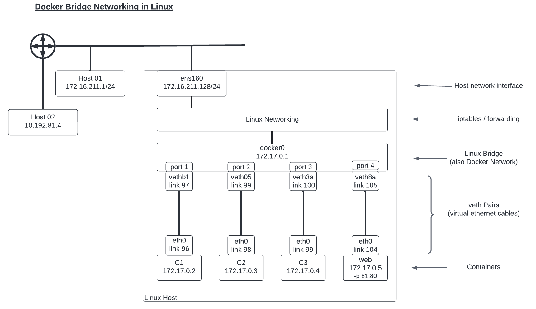
The additions to this topology drawing include:
- A fourth container called web has been added. This container is running a web server on port 80 that has been “published” (made available outside the container network) on port 81.
- The Linux host’s primary network link, ens160, with its IP address of 172.16.211.128 has been added.
- The network processing layer from Linux that provides routing, filtering, and other network functions has been added.
- Two additional hosts in the lab network outside of the Linux host running the containers have been shown, along with basic connectivity indications.
A ping in the dark…
We are going to start with a simple test to determine whether we can ping from one container to the primary IP address from the Linux host hosting the container. Specifically, from C1 to ens160’s IP address of 172.16.211.128.
root@c1:/# ping 172.16.211.128
PING 172.16.211.128 (172.16.211.128) 56(84) bytes of data.
64 bytes from 172.16.211.128: icmp_seq=1 ttl=64 time=1.80 ms
64 bytes from 172.16.211.128: icmp_seq=2 ttl=64 time=0.051 ms
64 bytes from 172.16.211.128: icmp_seq=3 ttl=64 time=0.092 ms
^C
--- 172.16.211.128 ping statistics ---
3 packets transmitted, 3 received, 0% packet loss, time 2021ms
rtt min/avg/max/mdev = 0.051/0.646/1.796/0.813 ms
The success is probably not all that surprising — or even feel that satisfying. I mean, we network engineers ping between two hosts all the time, right? So, why bother? Let me break it down for you.
First up, remember that the container and the Linux host are on 2 different layer 2 networks. The container is on 172.17.0.0/16, and the host is on 172.16.211.0/24. We would assume this type of traffic would involve routing. So let’s check the routing table on the involved devices.
The container’s table below shows us that the default route is used to reach the 172.16.211.0/24 network.
root@c1:/# ip route
default via 172.17.0.1 dev eth0
172.17.0.0/16 dev eth0 proto kernel scope link src 172.17.0.2
And the host’s table shows that there is actually a route for 172.17.0.0/16 through the docker0 interface.
root@expert-cws:~# ip route
default via 172.16.211.2 dev ens160 proto dhcp src 172.16.211.128 metric 100
172.16.211.0/24 dev ens160 proto kernel scope link src 172.16.211.128
172.16.211.2 dev ens160 proto dhcp scope link src 172.16.211.128 metric 100
172.17.0.0/16 dev docker0 proto kernel scope link src 172.17.0.1
Nothing seems out of the ordinary, but don’t leave just yet. I swear there is a point to this part of the exploration.
Let’s look at the packets themselves using the Linux tool tcpdump to monitor the icmp traffic on ens160.
root@expert-cws:~# tcpdump -n -i ens160 icmp
tcpdump: verbose output suppressed, use -v or -vv for full protocol decode
listening on ens160, link-type EN10MB (Ethernet), capture size 262144 bytes
I started up the capture and then issued another ping from C1 to the Linux host. But I didn’t see any packets captured on interface ens160 despite the pings being successful. See, I told you it might get interesting. ?
Let’s change our capture to the docker0 interface instead.
root@expert-cws:~# tcpdump -n -i docker0 icmp
tcpdump: verbose output suppressed, use -v or -vv for full protocol decode
listening on docker0, link-type EN10MB (Ethernet), capture size 262144 bytes
14:51:53.427337 IP 172.17.0.2 > 172.16.211.128: ICMP echo request, id 38, seq 1, length 64
14:51:53.427373 IP 172.16.211.128 > 172.17.0.2: ICMP echo reply, id 38, seq 1, length 64
Okay, that looks better. But, why are we seeing the traffic on the docker0 interface when the destination was the address assigned to the ens160 interface? Well, because the traffic never actually reaches the ens160 interface. The networking stack within the Linux system processes the traffic, and because it is all internal to the system, there is no need for the traffic to make it to the network link/adapter.
Then why does it show up on the docker0 interface at all? Why can’t the networking stack just process it directly and leave all “interfaces” out of it? This is because of the network isolation that is used as part of Docker networking. Recall back to Part 1; how when we ran ip link from within the container, we only saw the container interface and not the other interfaces from the host. And when we ran the command from the host, we did NOT see the container interfaces in the list. We only saw the host side of the veth pair. As a reminder, here is the command from the container host.
root@expert-cws:~# ip link
1: lo: <LOOPBACK,UP,LOWER_UP> mtu 65536 qdisc noqueue state UNKNOWN mode DEFAULT group default qlen 1000
link/loopback 00:00:00:00:00:00 brd 00:00:00:00:00:00
2: ens160: <BROADCAST,MULTICAST,UP,LOWER_UP> mtu 9000 qdisc mq state UP mode DEFAULT group default qlen 1000
link/ether 00:0c:29:75:99:27 brd ff:ff:ff:ff:ff:ff
3: docker0: <BROADCAST,MULTICAST,UP,LOWER_UP> mtu 1500 qdisc noqueue state UP mode DEFAULT group default
link/ether 02:42:9a:0c:8a:ee brd ff:ff:ff:ff:ff:ff
97: vethb192fa8@if96: <BROADCAST,MULTICAST,UP,LOWER_UP> mtu 1500 qdisc noqueue master docker0 state UP mode DEFAULT group default
link/ether 46:10:b9:df:52:8b brd ff:ff:ff:ff:ff:ff link-netnsid 0
99: veth055569e@if98: <BROADCAST,MULTICAST,UP,LOWER_UP> mtu 1500 qdisc noqueue master docker0 state UP mode DEFAULT group default
link/ether 52:07:4f:3e:11:c6 brd ff:ff:ff:ff:ff:ff link-netnsid 1
101: veth3a3ee0b@if100: <BROADCAST,MULTICAST,UP,LOWER_UP> mtu 1500 qdisc noqueue master docker0 state UP mode DEFAULT group default
link/ether 9e:51:13:75:53:52 brd ff:ff:ff:ff:ff:ff link-netnsid 2
105: vethd8a9fa5@if104: <BROADCAST,MULTICAST,UP,LOWER_UP> mtu 1500 qdisc noqueue master docker0 state UP mode DEFAULT group default
link/ether d2:86:8f:ab:75:0b brd ff:ff:ff:ff:ff:ff link-netnsid 3
The blue link number 97 represents the host side of the veth that connects to link number 96 on C1. But where is link number 96 in the list?
Linux network namespaces enter the story
The answer is that link number 96, the eth0 interface for C1, is in a different network namespace from the default one from the other links on the host.
Linux namespaces are an abstraction within Linux that allow system resources to be isolated from each other. Namespaces can be set up for many different types of resources including processes, mount points, and networks. In fact, these namespaces are key to how Docker containers run as isolated instances from each other and the host they run on.
We can view the network namespaces on our host with the list namespaces command.
root@expert-cws:~# lsns --type=net
NS         TYPE  NPROCS PID    USER   NETNSID    NSFS COMMAND
4026531992 net   375    1      root   unassigned /run/docker/netns/default /sbin/init maybe-ubiquity
4026532622 net   1      81590  uuidd  unassigned /usr/sbin/uuidd --socket-a
4026532675 net   1      1090   rtkit  unassigned /usr/libexec/rtkit-daemon
4026532749 net   2      134263 expert unassigned /usr/share/code/code --typ
4026532808 net   1      267673 root   0          /run/docker/netns/74fa6636a15f bash
4026532872 net   1      267755 root   1          /run/docker/netns/e12672b07df8 bash
4026532921 net   6      133573 expert unassigned /opt/google/chrome/chrome
4026532976 net   1      133575 expert unassigned /opt/google/chrome/nacl_he
4026533050 net   1      267840 root   2          /run/docker/netns/5cab1255c9ae bash
4026533115 net   1      268958 root   3          /run/docker/netns/c54dcb1bd674 /bin/bash
Each of the entries in the list colored blue represents one of the four containers that we are running now, with the PID column identifying the specific process tied to the unique container. We can determine the PID for a container by inspecting it.
root@expert-cws:~# docker inspect c1 | jq .[0].State.Pid
267673
And with that, we can now run the command to view the network links from within the container’s network namespace.
root@expert-cws:~# nsenter -t 267673 -n ip link
1: lo: <LOOPBACK,UP,LOWER_UP> mtu 65536 qdisc noqueue state UNKNOWN mode DEFAULT group default qlen 1000
link/loopback 00:00:00:00:00:00 brd 00:00:00:00:00:00
96: eth0@if97: <BROADCAST,MULTICAST,UP,LOWER_UP> mtu 1500 qdisc noqueue state UP mode DEFAULT group default
link/ether 02:42:ac:11:00:02 brd ff:ff:ff:ff:ff:ff link-netnsid 0
And BAM! There we have link number 96.
And this brings us back to the question: why didn’t the host network stack process the ping directly from the container? Why do we see the traffic on the docker0 interface? Because the networking “stack” is really the network namespace. And the container’s network namespace where the ping originated is different from the default network namespace where the IP address for the ens160 interface resides. It is the virtual ethernet “cable” that allows traffic from the container namespace to reach the default namespace, through the docker0 interface. And once the traffic arrives in the docker0 interface, the networking stack can now process the request and send the reply, all through the docker0 interface.
Pinging beyond the gates… er host
So we’ve now seen how network isolation is accomplished with Linux namespaces and the impact on the interfaces involved in the network processing of traffic. For our next test, let’s send traffic outside of the Linux host where our containers are running, and send a ping to another Host01 from the network topology.
root@c1:/# ping -c 1 172.16.211.1
PING 172.16.211.1 (172.16.211.1) 56(84) bytes of data.
64 bytes from 172.16.211.1: icmp_seq=1 ttl=63 time=0.271 ms

--- 172.16.211.1 ping statistics ---
1 packets transmitted, 1 received, 0% packet loss, time 0ms
rtt min/avg/max/mdev = 0.271/0.271/0.271/0.000 ms
I actually sent a single ping packet from the container, and we can see that it was successful. Before sending the ping I started up a packet capture on both the docker0 and ens160 interfaces to capture the traffic along the way and compare the differences as the traffic arrived in the default network namespace from the container and as it was sent out from the host towards its destination (as well as the return trip).
# Capture on the docker0 interface
root@expert-cws:~# tcpdump -n -i docker0 icmp
tcpdump: verbose output suppressed, use -v or -vv for full protocol decode
listening on docker0, link-type EN10MB (Ethernet), capture size 262144 bytes

17:11:13.047823 IP 172.17.0.2 > 172.16.211.1: ICMP echo request, id 41, seq 1, length 64
17:11:13.048061 IP 172.16.211.1 > 172.17.0.2: ICMP echo reply, id 41, seq 1, length 64

# Capture on the ens160 interface
root@expert-cws:~# tcpdump -n -i ens160 icmp
tcpdump: verbose output suppressed, use -v or -vv for full protocol decode
listening on ens160, link-type EN10MB (Ethernet), capture size 262144 bytes

17:11:13.047856 IP 172.16.211.128 > 172.16.211.1: ICMP echo request, id 41, seq 1, length 64
17:11:13.048024 IP 172.16.211.1 > 172.16.211.128: ICMP echo reply, id 41, seq 1, length 64
Take a look at the output above. The blue lines are the echo requests sent from the container, and the green lines are the echo replies from the other host. The bold purple addresses in the requests represent the source addresses from the container, and the bold orange addresses indicate the destination addresses for the reply packets. On the docker0 captures, the addresses shown are the IP addresses assigned to the C1 interface — this would be expected. However, on the ens160 capture, the addresses have been translated to the IP address of the Linux host machine’s ens160 interface.
That is right, our old friend Network Address Translation (NAT) shows up in container networking as well. In fact, so does NAT’s very useful cousin PAT (Port Address Translation), but I’m getting ahead of myself.
Entering the Docker networking story… iptables!
The networks created by Docker to support a bridge-type network are built to be private and to leverage IP address space that is NOT reachable from outside the Docker-managed network. However, many services deployed and managed with Docker do require connectivity beyond the small number of containers making up the service and running on the host. Docker leverages the same network concept used elsewhere to solve this problem, Network (and Port) Address Translation (NAT/PAT). And similar to how we’ve seen Docker leveraging Linux elements like bridges and namespaces, Docker makes use of iptables to perform the address translation and filtering involved here as well.
Before we start looking at how iptables are involved in these traffic flows, I wanted to give a quick caveat. Network traffic processing and flow through the underbelly of Linux is a complicated topic, and iptables is both a powerful and complicated tool. I plan to break down the topic here in the blog to describe and explain what is happening under the hood of Docker networking in as simple and clear a way as possible. But a thorough exploration of iptables and Linux networking would be worthy of several blog posts on their own.
With iptables, rules are created and applied to the processing of network traffic as it is handled by Linux. These rules are applied at different points in the processing of traffic to accomplish a number of different tasks. Rules can be applied:
- Before any routing decision is made (PREROUTING).
- As traffic destined for the local host arrives (INPUT).
- As traffic created by the local host is sent (OUTPUT).
- As traffic “passing through” the local host is processed (FORWARD).
- After the routing decision is made (POSTROUTING).
And the rules that are written can do a number of things to the traffic.
- Traffic can be blocked/denied.
- Traffic can be allowed/permitted.
- Traffic can be redirected elsewhere.
- Traffic can have its source or destination addresses changed (NAT/PAT).
Rules are added to one of the “tables” that iptables manages. The two tables worth mentioning now are the filter and the nat tables. The filter table creates rules primarily concerned with whether traffic is allowed or blocked, while the nat table has rules related to address translation. Let’s look at the nat table and see if we can find what caused the translation of the ICMP traffic from our example.
root@expert-cws:~# iptables -L -v -t nat
Chain PREROUTING (policy ACCEPT 251 packets, 67083 bytes)
 pkts bytes target     prot opt in     out     source               destination
   18  1292 DOCKER     all  --  any    any     anywhere             anywhere             ADDRTYPE match dst-type LOCAL

Chain INPUT (policy ACCEPT 247 packets, 66747 bytes)
 pkts bytes target     prot opt in     out     source               destination

Chain OUTPUT (policy ACCEPT 19468 packets, 1264K bytes)
 pkts bytes target     prot opt in     out     source               destination
    3   252 DOCKER     all  --  any    any     anywhere            !localhost/8          ADDRTYPE match dst-type LOCAL

Chain POSTROUTING (policy ACCEPT 19472 packets, 1264K bytes)
 pkts bytes target     prot opt in     out     source               destination
   31  1925 MASQUERADE  all  --  any    !docker0  172.17.0.0/16        anywhere

Chain DOCKER (2 references)
 pkts bytes target     prot opt in     out     source               destination
    7   588 RETURN     all  --  docker0 any     anywhere             anywhere
Look at the rule in the POSTROUTING table colored blue. This is the rule that caused the translation we saw. Now, let’s break down the parts of the rule that are used to match traffic to process.
- protocol = all
- Match traffic of any protocol type
- in = any / out = !docker0
- Match traffic coming IN any interface and going OUT any interface other than docker0
- Traffic going OUT docker0 would be sent towards a container
- source = anywhere / destination = anywhere
- Match traffic from or to any address
The “target = MASQUERADE” part describes the action this rule will take. You might be more familiar with the actions like DROP or ACCEPT that show up on the filter table, but the NAT table was a different set of targets that indicate the type of translation that will occur. MASQUERADE is a type of source address translation (SNAT) that translates the source network address of the traffic to the address assigned to the interface the traffic has been routed OUT.
Consider the echo request sent from the container against this rule.
- An echo request matches the “all protocol.”
- The packet came in the docker0 interface (in = any) and will be going out the ens160 (out = !docker0).
- The source and destination are certainly “anywhere.”
When the traffic was processed against this rule the MASQUERADE target/action was taken to SNAT the source address to the IP address of the ens160 interface — which is exactly what we saw happen.
Look out! There is a web (server) ahead!
So far we’ve used some ICMP traffic with ping to look at how containers can reach external networks and hosts. But, what about when a container is running a service like a web server that is designed to be available to external users? Let’s end our discussion with this example. In order to get started, we’re going to need a web server.
There is a multitude of web servers that can be run as Docker containers, but for our exploration here, I’m going to keep it very simple and use the HTTP server that is included with Python and the standard “python:3” Docker image maintained by the Python Software Foundation and Docker.
# Start the container in the background
root@expert-cws:~# docker run -tid --rm \
  			--name web --hostname web \
  			-p 172.16.211.128:81:80 \
  			python:3 /bin/bash

# Attach to the running container
root@expert-cws:~# docker attach web

# Start a basic web server
root@web:/# python -m http.server 80
Serving HTTP on 0.0.0.0 port 80 (http://0.0.0.0:80/) ...
The “docker run” command should be familiar from when we ran commands in Part 1, but there is a new option included. We need to “publish” the container’s ports which need to be made available to external hosts. A container can have no ports published, or many dozens of ports depending on the unique needs of that service.
In the command above, I am publishing port 80 from the container to port 81 on the host server’s IP address of 172.16.211.128.
If I had left off the IP address to publish the service to, Docker would have made the web server available on any/all IP addresses on the underlying host. Leaving off an explicit IP address for publishing a service is common, however I find being explicit a better strategy. This is somewhat of a personal preference in application design.
I can now attempt to access the web server from Host01.
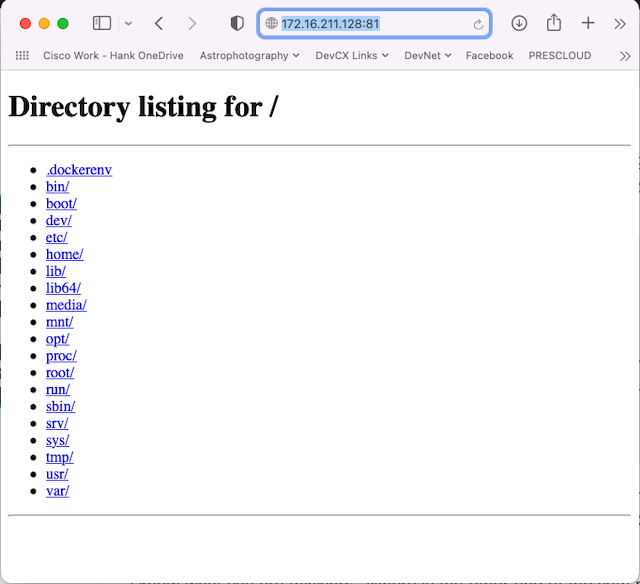
Excellent, by browsing to the IP address of the Linux host on port 81 I am greeted with a direct listing from the container where the Python web server is running.
Tracing the web traffic with packets and tables
Let’s finish our exploration today by inspecting the traffic for the incoming web traffic and the translation rules that connect things together.
We need to change up our packet capture commands to capture the web traffic on both the ens160 and docker0 interfaces. As traffic arrives at the Linux host it will be destined to tcp port 81 and translated to tcp port 80, before it is sent out to the container.
# Capture traffic from the Linux host interface
root@expert-cws:~# tcpdump -n -i ens160 'tcp port 81'
tcpdump: verbose output suppressed, use -v or -vv for full protocol decode
listening on ens160, link-type EN10MB (Ethernet), capture size 262144 bytes

18:34:59.147085 IP 172.16.211.1.64534 > 172.16.211.128.81: Flags [SEW], seq 3761281905, win 65535, options [mss 1460,nop,wscale 6,nop,nop,TS val 1727838954 ecr 0,sackOK,eol], length 0
18:34:59.147191 IP 172.16.211.128.81 > 172.16.211.1.64534: Flags [S.E], seq 3294439992, ack 3761281906, win 65160, options [mss 1460,sackOK,TS val 3650251894 ecr 1727838954,nop,wscale 7], length 0
.
.


# Capture traffic being sent to the containers
root@expert-cws:~# tcpdump -n -i docker0 'tcp port 80'
tcpdump: verbose output suppressed, use -v or -vv for full protocol decode
listening on docker0, link-type EN10MB (Ethernet), capture size 262144 bytes


18:34:59.147133 IP 172.16.211.1.64534 > 172.17.0.5.80: Flags [SEW], seq 3761281905, win 65535, options [mss 1460,nop,wscale 6,nop,nop,TS val 1727838954 ecr 0,sackOK,eol], length 0
18:34:59.147178 IP 172.17.0.5.80 > 172.16.211.1.64534: Flags [S.E], seq 3294439992, ack 3761281906, win 65160, options [mss 1460,sackOK,TS val 3650251894 ecr 1727838954,nop,wscale 7], length 0
.
.
I have limited the output in the post above to just the start of the request where we can see the translation at work.
In the output above, the blue lines represent the initial request packet from the web browser to the server, and the green lines are the first packet sent to establish the session. By looking at the bold purple and orange addresses, you can see the destination address translation (DNAT) at work in the communications. The source addresses are left unchanged, and in fact, in the below logs from the container, you can see the IP address from Host01.
root@web:/# python -m http.server 80
Serving HTTP on 0.0.0.0 port 80 (http://0.0.0.0:80/) ...
172.16.211.1 - - [07/Sep/2022 18:30:07] "GET / HTTP/1.1" 200 -
We can once again look at the NAT table using iptables and find the rule that provides this behavior.
root@expert-cws:~# iptables -L -v -t nat -n
Chain PREROUTING (policy ACCEPT 42 packets, 4004 bytes)
 pkts bytes target     prot opt in     out     source               destination
   38  2712 DOCKER     all  --  *      *       0.0.0.0/0            0.0.0.0/0            ADDRTYPE match dst-type LOCAL

Chain INPUT (policy ACCEPT 37 packets, 3584 bytes)
 pkts bytes target     prot opt in     out     source               destination

Chain OUTPUT (policy ACCEPT 15523 packets, 1010K bytes)
 pkts bytes target     prot opt in     out     source               destination
   17  1092 DOCKER     all  --  *      *       0.0.0.0/0           !127.0.0.0/8          ADDRTYPE match dst-type LOCAL

Chain POSTROUTING (policy ACCEPT 15530 packets, 1010K bytes)
 pkts bytes target     prot opt in     out     source               destination
   42  2849 MASQUERADE  all  --  *      !docker0  172.17.0.0/16        0.0.0.0/0
    0     0 MASQUERADE  tcp  --  *      *       172.17.0.5           172.17.0.5           tcp dpt:80

Chain DOCKER (2 references)
 pkts bytes target     prot opt in     out     source               destination
   14  1176 RETURN     all  --  docker0 *       0.0.0.0/0            0.0.0.0/0
    7   448 DNAT       tcp  --  !docker0 *       0.0.0.0/0            172.16.211.128       tcp dpt:81 to:172.17.0.5:80
The rule in blue has the target set to DNAT along with a destination of 172.16.211.128 and translation of “tcp dpt:81 to:172.17.0.5:80“. The rule is applied both during the PREROUTING and OUTPUT phases of network processing by using the ability within iptables to TARGET another chain in the link.
A quick stop at the filter table
There is one final stop in our exploration of the traffic flows I want to make before finishing up. So far our iptables commands have targeted the NAT table (-t nat). Let’s take a look at the filter table where the ACCEPT/DROP rules are found.
root@expert-cws:~# iptables -L -v -t filter -n
Chain INPUT (policy ACCEPT 231K packets, 26M bytes)
 pkts bytes target     prot opt in     out     source               destination

Chain FORWARD (policy DROP 0 packets, 0 bytes)
 pkts bytes target     prot opt in     out     source               destination
  141 15676 DOCKER-USER  all  --  *      *       0.0.0.0/0            0.0.0.0/0
  141 15676 DOCKER-ISOLATION-STAGE-1  all  --  *      *       0.0.0.0/0            0.0.0.0/0
39461  118M ACCEPT     all  --  *      docker0  0.0.0.0/0            0.0.0.0/0            ctstate RELATED,ESTABLISHED
   13   952 DOCKER     all  --  *      docker0  0.0.0.0/0            0.0.0.0/0
30852 1266K ACCEPT     all  --  docker0 !docker0  0.0.0.0/0            0.0.0.0/0
    6   504 ACCEPT     all  --  docker0 docker0  0.0.0.0/0            0.0.0.0/0

Chain OUTPUT (policy ACCEPT 215K packets, 18M bytes)
 pkts bytes target     prot opt in     out     source               destination

Chain DOCKER (1 references)
 pkts bytes target     prot opt in     out     source               destination
    7   448 ACCEPT     tcp  --  !docker0 docker0  0.0.0.0/0            172.17.0.5           tcp dpt:80

Chain DOCKER-ISOLATION-STAGE-1 (1 references)
 pkts bytes target     prot opt in     out     source               destination
30852 1266K DOCKER-ISOLATION-STAGE-2  all  --  docker0 !docker0  0.0.0.0/0            0.0.0.0/0
70326  120M RETURN     all  --  *      *       0.0.0.0/0            0.0.0.0/0

Chain DOCKER-ISOLATION-STAGE-2 (1 references)
 pkts bytes target     prot opt in     out     source               destination
    0     0 DROP       all  --  *      docker0  0.0.0.0/0            0.0.0.0/0
30852 1266K RETURN     all  --  *      *       0.0.0.0/0            0.0.0.0/0

Chain DOCKER-USER (1 references)
 pkts bytes target     prot opt in     out     source               destination
70326  120M RETURN     all  --  *      *       0.0.0.0/0            0.0.0.0/0
Most of the DOCKER-related aspects found in the filter table are there to ensure the network isolation of containers. However the rule in blue that I have indicated above is key to how services are exposed from a container to the outside world. This rule will ACCEPT tcp port 80 traffic destined for 172.17.0.5 (the web container) that arrives on any interface other than docker0 and goes out interface docker0. This rule uses the container’s actual IP address and port because the filtering happens after the DNAT from the NAT table.
The light at the end of the default Docker networking journey
And so we find ourselves at the end of this exploration of the default Docker Networking. Looking around the group, I’m glad to see that we didn’t lose anyone along the way, but I know it was a close one. And you might not believe me, but even after another 3,500 words on the topic of Docker networking (a total of over 7,000 between Parts 1 and 2), there is plenty more to explore on the topic. Overlay networks, how DNS works for containers, custom network plugins, and (gasp) Kubernetes networking are all out there for you to explore!
My goal for this short series was to help give a foundation on which you can continue to build your knowledge around container networking and to make the topic less mysterious or daunting for network engineers new to it. It can be very easy to become intimidated when working through container introductions that “just work” but don’t explain “why they work” or “how they work.” If I did my job right, the magic isn’t so magical anymore.
Here are a few links to other resources worth checking out for more information on the topic.
- In Season 2 of NetDevOps Live, Matt Johnson joined me to do a deep dive into container networking. His session was fantastic, and I reviewed it when getting ready for this post. I highly recommend it as another great resource.
- The Docker documentation on networking is very good. I referenced it quite often when putting this post together.
- The man pages for Linux namespaces and iptables are excellent resources about these important technologies that enable Docker networking
- And check out the man page for tcpdump if you’d like to do more packet capturing
And as always, please let me know what you thought of this post in the comments or over on Twitter. What should I “explore” next here on the blog? Thanks for reading!
Follow Cisco Learning & Certifications
Twitter | Facebook | LinkedIn | Instagram
Use #CiscoCert to join the conversation.


nice port Hank, bookmarked
Thanks Mrigank!
Excellent follow up from your part 1. I hope you plan to continue the conversation by touching on Kubernetes networking
Thanks Eric!
I’m probably going to tackle another topic in the next few blogs, but I would love to dive into Kubernetes networking as well. So many topics, so little time 🙂
Interesante implementar Docker en una red.
Linux distros are moving away from iptables to nftables, and Red Hat is promoting their Podman(default to Rootless) to replace insecure-by-default Rootful Docker, I read better IPv6 support: https://www.redhat.com/sysadmin/podman-new-network-stack
Can I join you
It’s time to check out podman networking
I haven’t looked at podman at all yet. Never enough time for everything :-).
I would like to be successful in my life with your helping also to be in you country
Wow Hank! Thanks for this detailed blog entry.
You are welcome Kevin!
Nice Work
Thanks so much!
I look forward to more information – Nice Job with the explanation.
Oh, there’s so much more information to come!
Thanks
You are welcome Steven, thanks for reading.
I look forward to more information – Nice Job with the explanation.
You are welcome!
Thank you for sharing!
You are welcome! Thanks for stopping by to check it out.
Nice work
Nice, lots to learn.
good coverage of IPtables as you say a complex topic
Thanks. It’s a decent start, but there is a lot in that topic.
Good post
Nice, this has been a great review of dockers networking! Looking forward the the next installment.
Glad you found it useful!
Interesting reading, thx for sharing.
You are welcome. Thanks for reading.
great topic about docker networking
Thanks! I love how much “networking” is in container/Docker networking concepts. You just need to dive in.
Interesting read about docker; the first time I read something like this. Nice reading
Glad to have had something to bring you in!
Thank you for sharing!
Great stuff Hank, Bookmarking this one!
I often go back to some of my own posts as reminders of how things work. They make great notes on tech.
Thanks Hank
Great content!
Nice Information, thanks!
nice work and excellent information.
Very detailed blog entry. Well done
Thanks! I always worry that my blogs might get too long/technical. Glad they are appreciated.
Very technically insightful.
Great information about a fantastic tool! Well done!
Docker is a great tool built on top of a lot of other great tools and concepts present in Linux for a long time.
Great content as always Hank!
nice work great reading it , and excellent information.
Great article, thanks.
I have heard about Docker for so long but never really understood it very well. This blog really helps put it in focus!
Glad to have helped Docker become a little clearer!
I enjoyed the technical breadth of this article. Great content that will be useful for future reference.
Excellent! I know I’ll be back to this post next time I need to understand or troubleshoot something related to container networking.
This is a great read, as I don’t currently understand docker networking and I just know that our organization and it’s developers are going to need help to implement/run systems built on it soon. Thanks!
Did you check out Part 1 as well (https://blogs.cisco.com/learning/exploring-default-docker-networking-part-1)? It might be useful too.
Useful info, bookmarked !! (and thank you)
Great content, thanks
Interesting, thank you for the overview.
Looks like Linux and Cisco APIs in XE or above is now the requirements.
Excellent follow up from your part 1
Thank you.
Great Blog, thank you
Thanks!!!
The new ways of integrating componets in the network are mind boggeling!
Every time I learn something new I feel a bit mind boggled. But container networking isn’t any more mind boggling than learning BGP, Frame Relay, or any other new technology that I have had to along the way. And less boggling than some. I’m looking at you multicast routing and QoS 🙂
You are an inspiration Hank!
Interesting reading, thanks for sharing.
Lots to digest especially as more Cisco products (anything Webex related) are now utilising Docker under the hood, Its great to be able to gain a better insight/understanding on how it all works…
I’ll be heading back to these blog series a few times to go though it again and understand it better…
Thanks Philip. Indeed, Docker is becoming a pervasive technology in all areas of IT. Having an understanding of how it works helps build confidence when working with new technologies.
Very useful, thank you for your time and effort.
Very very useful!!
great info!!
I would like to be successful in my life with your helping. Nice one
Great Learning Content
Great, thanks for sharing
Nice one as always @Hank, I am keen to if we take this to the next level and release a dockerized router or swich 🙂
Thanks. I’m curious myself on whether we’ll see significant need and desire for something akin to a traditional router/switch to replace the underlying Linux networking concepts that containers rely on. I could probably debate either side of that question. Time will tell!
I don’t fully understand this concept in terms of L2 and L3 encapsulation at the hops from the source container to the destination IP address. If the ICMP packet from a container isn’t captured on the ens160 interface, would a payload from a container sent to the ens160 interface reach the ens160 interface as a frame, after Linux networking processes the packet?
I agree it doesn’t seem like it should be the case, but as we saw in my testing above in the section “A ping in the dark…”, pings to the IP address assigned to the ens160 interface on the host are NOT captured on the ens160 interface.
I think about it this way.
Capturing traffic on an interface is done somewhere just before/after the traffic is received/sent at the interface. So it happens “below” the IP layer where ICMP is processed.
Because Linux networking can process the ICMP packet, and send the reply, without needing to send it “down the stack towards the actual interface” it never makes it to where tcpdump is processing traffic for capture.
Using your terms of packet/frame – the ICMP “packet” is never encapsulated in a L2 “frame” at the ens160 interface to be captured.
Hopefully that helps you understand it better. I’m forever fascinated by the low level processing of how traffic flows. It isn’t always relevant in day to day work and network engineering, but it can certainly help you understand things better when you need to really get dirty in troubleshooting something.
If packets from C1 were sent to Host 01, then as packets they would egress the ens160 interface?
Yes, that is correct. Any traffic destined to another host will egress the ens160 interface and be picked up and visible in packet captures. You can see this difference in the blog post section called “Pinging beyond the gates… er host”.
Very comprehensive, will need to re-read it to fully digest – Thank you!
Well presented. Thanks.
Great intro, I need to dive more into containers soon!
Great blog, thank you for sharing!
Great read love the way you break it down. Thanks.
That is the good guidance.
Great information. This helped me out a lot.
Great information, Thanks!
Thank you !
Saved to my bookmarks.. Thank you!
Bookmarked for future reference.
Great information, thanks for sharing!