
It’s Halloween — a time for too much candy, scary movies, kids in fun costumes, and lots of tricks and treats. As I thought about what to write for my blog this month, I quickly went to one of the scariest things for every network engineer: SPANNING TREE!!!! That’s right… can anything else bring the same level of dread and cold sweats as the potential for a bridging loop?!
Fear not. With a bit of good practical design and configuration practices, spanning tree doesn’t have to be scary. However, even the best engineers (or moderately decent ones like myself) can forget a best practice or two. Let me set the spooky scene for you…
It was a dark and stormy night…
The following anecdote took place about three or four years ago when I was part of the DevNet Sandbox team. We had recently stood up a new data center for hosting labs, and I had returned home from California after spending several weeks onsite, standing up the network and systems at the data center. I was feeling quite good about how well things had gone. Particularly, the speed and efficiency we were able to bring things online, thanks to a heavy amount of automation and programmability. In retrospect, I should have known something was going to go wrong…
I think the first sign there might be a problem in the network was when I noticed my remote connection into the new location started to get really laggy. I even got disconnected from some servers. It would clear up fairly quickly. But when the issues repeated several times, I started to wonder what might be the cause.
I checked other monitoring systems. Intermittent network issues had recently started showing up; slow response from systems, occasional disconnects that would clear up fairly quickly, that sort of thing. Nothing overly drastic, but they certainly were symptoms that indicated something might not be perfectly healthy in the network. I began to poke around a bit more. Eventually, I stumbled across a few things that pointed to a possible issue somewhere in the layer 2 parts of the network.
It was quite a while ago, so the details are a little fuzzy. I think I was on one of the top of rack Nexus 9000 switches in a hardware hosting rack when syslog messages hit the terminal about MAC flapping occurring. Now, MACs will move around a network occasionally. However, a flapping MAC address happens when a switch sees it changing back and forth between two ports. This is not normal. It often points to a network loop — something spanning tree is supposed to prevent from occurring.
Here is an example syslog message related to MAC Flapping:
After a bit more troubleshooting, I also noticed that the network was reconverging spanning tree, changing the root bridge over and over again. This was definitely a problem. Even “rapid” spanning tree convergence is noticeable to network users who find themselves waiting for a port to transition to forwarding after ports change state.
Explore how Loop Detection Guard prevents network loops on Catalyst 9000 switches. Read “Preventing Network Loops! A Feature You Need to be Aware of” now.
Enough of the trick already, Hank… where’s the treat?
Long story short, the root of the problem (pun TOTALLY intended) was a new physical switch that was being added to the network for one of the hardware labs we were setting up.
The new switch hadn’t been fully configured for its new role yet, and the upstream switches it was connected to already had the ports enabled in preparation for the new lab gear being added. The lab topology had multiple ports connected between this new switch and the data center fabric for different purposes and networks, but none of the final configuration had been applied yet. There were actually some remnants of old configuration applied to the switch, which resulted in the bridging loop and MACFLAP log messages.
Furthermore, this switch had previously served as the spanning tree root in a previous network and had a lower (i.e., better) priority than the actual spanning-tree root in our data center. Between connections being made/removed, ports getting errdisabled for different reasons, and other instabilities, the root was bouncing between this new switch and the main distribution switches in the data center every couple of minutes.
I was able to quickly stop the problems from occurring by shutting down the ports connected to this new switch until it was correctly configured and ready to be made an active part of the network. So, problem solved… kinda.
The bigger problem was that I had overlooked the critical spanning tree design and best practices for the configuration step in bringing the new data center network up and online. Had I remembered my fundamentals, this problem wouldn’t have happened: The network would have automatically blocked ports that were behaving in unexpected ways.
You are NOT root: Preventing unexpected root bridges with root guard
Consider this very simple triangle of switches as a quick review of the importance of the root bridge in a spanning-tree network.
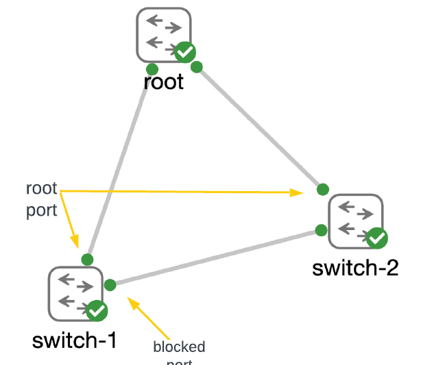
Switches connected together with layer 2 links use BPDUs (bridge protocol data units) to learn about each other and determine where the “root” of the spanning tree will be placed. The switch that has the best (i.e., lowest) priority becomes root. With the root bridge identified, switches begin the process of breaking loops in the network by blocking ports that spanning tree identifies as having the worst priority on redundant links.
A full discussion on the spanning-tree process for building the tree is out of scope for this blog post. It is a very important topic for network engineers to understand, so I might return to spanning tree in future blog posts. If you’d like to dive deeper into the topic now, check out our CCNA and ENCOR courses.
The process of electing the root bridge and converging on a loop-free network can take tens of seconds to even a minute (or more) in large networks, depending on which version of spanning tree is used and how well the network is designed. During the process of convergence, the network prevents bridging loops by defaulting to blocking traffic on ports. This will result in significant disruption to any users and applications that are actively using the network. Remember in my example above, how my network access had gotten “laggy” and my connections had even become disconnected? As long as the root bridge remains stable and does NOT change, adding a new switch to a network is a non-disruptive activity.
So, how does a network engineer prevent the root bridge from changing in the network? I’m glad you asked.
Identifying the root bridge for the network
The first step is to look at the network design and identify which switch makes the most logical sense to be the root, explicitly configuring it to have the best (i.e., lowest) priority. Here, I configure my root switch to run rapid per-vlan spanning tree (rapid-pvst) and set the priority to 16384.
root#show run | sec spanning

spanning-tree mode rapid-pvst
spanning-tree extend system-id
spanning-tree vlan 1-4094 priority 16384


root#show span

VLAN0001
  Spanning tree enabled protocol rstp
  Root ID    Priority    16385
             Address     5254.000e.dde8
             This bridge is the root
             Hello Time   2 sec  Max Age 20 sec  Forward Delay 15 sec

  Bridge ID  Priority    16385  (priority 16384 sys-id-ext 1)
             Address     5254.000e.dde8
             Hello Time   2 sec  Max Age 20 sec  Forward Delay 15 sec
             Aging Time  300 sec

Interface           Role Sts Cost      Prio.Nbr Type
------------------- ---- --- --------- -------- --------------------------------
Gi0/1               Desg FWD 4         128.2    P2p
Gi0/2               Desg FWD 4         128.3    P2p
Gi0/3               Desg FWD 4         128.4    P2p
Note: With “per-vlan spanning-tree” every VLAN will have its own spanning-tree constructed. The priority of each bridge is the configured priority plus the VLAN number. So for VLAN 1, the priority is 16384+1 or 16385.
If we look at the spanning-tree state on one of the other switches in the network, we can confirm the root bridge and the creation of a loop-free network.
switch-1#show span

VLAN0001
  Spanning tree enabled protocol rstp
  Root ID    Priority    16385
             Address     5254.000e.dde8
             Cost        4
             Port        2 (GigabitEthernet0/1)
             Hello Time   2 sec  Max Age 20 sec  Forward Delay 15 sec

  Bridge ID  Priority    32769  (priority 32768 sys-id-ext 1)
             Address     5254.0017.ae37
             Hello Time   2 sec  Max Age 20 sec  Forward Delay 15 sec
             Aging Time  300 sec

Interface           Role Sts Cost      Prio.Nbr Type
------------------- ---- --- --------- -------- --------------------------------
Gi0/1               Root FWD 4         128.2    P2p
Gi0/2               Desg FWD 4         128.3    P2p
Gi0/3               Altn BLK 4         128.4    P2p

switch-1#show cdp neighbors gigabitEthernet 0/1

Device ID        Local Intrfce     Holdtme    Capability  Platform  Port ID
root             Gig 0/1           146             R S I            Gig 0/1
If you compare the address of the root bridge shown on switch-1 to the output above from root, you will see that the Address and Priority for the root bridge match. Also, notice that interface G0/1 has the role of “Root” — this is the interface on the switch that has the best path back to the root bridge. And as the output from CDP shows, it is actually directly connected to the root.
Stopping a new root on the block… err, network
Identifying an intended root bridge for your network is great, but it doesn’t prevent a newly added switch from causing trouble.
Consider back to my example from my anecdote where a new switch was being added to the network that had previously been configured as the root in another network. While it could be argued that it is best practice and important to clear old configuration from a switch before adding it to the network, the reality is… things like this happen. It is important to engineer a network to handle events like this.
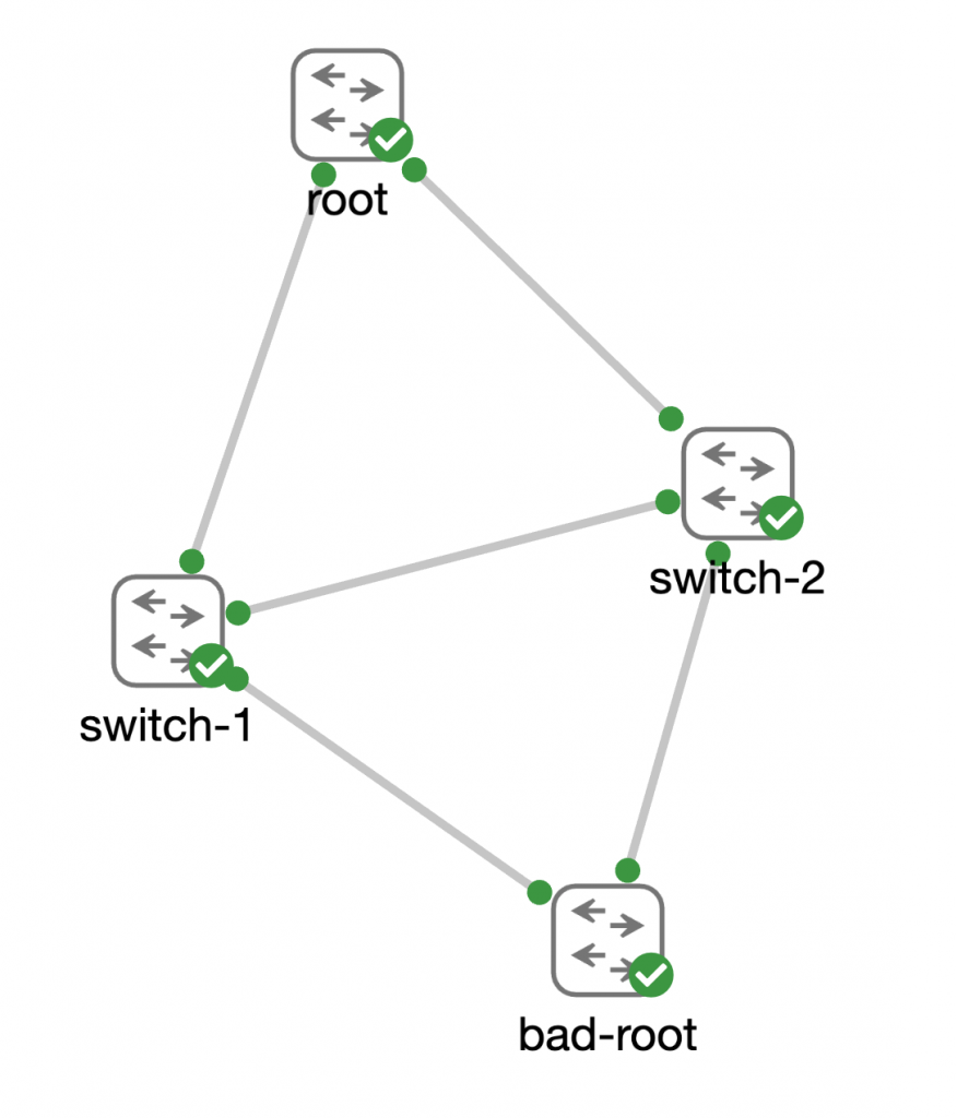
First, let’s see what happens to the spanning-tree network when bad-root is cabled into the network without any extra configuration protecting the spanning-tree network.
switch-1#show span

VLAN0001
  Spanning tree enabled protocol rstp
  Root ID    Priority    4097
             Address     5254.001e.82a2
             Cost        4
             Port        1 (GigabitEthernet0/0)
             Hello Time   2 sec  Max Age 20 sec  Forward Delay 15 sec

  Bridge ID  Priority    32769  (priority 32768 sys-id-ext 1)
             Address     5254.0017.ae37
             Hello Time   2 sec  Max Age 20 sec  Forward Delay 15 sec
             Aging Time  300 sec

Interface           Role Sts Cost      Prio.Nbr Type
------------------- ---- --- --------- -------- --------------------------------
Gi0/0               Root FWD 4         128.1    P2p
Gi0/1               Desg FWD 4         128.2    P2p
Gi0/2               Desg FWD 4         128.3    P2p
Gi0/3               Altn BLK 4         128.4    P2p


switch-1#show cdp neighbors gigabitEthernet 0/0

Device ID        Local Intrfce     Holdtme    Capability  Platform  Port ID
bad-root         Gig 0/0           154             R S I            Gig 0/1

Total cdp entries displayed : 1
Notice how the address and priority for the root bridge have changed, and that port Gi0/0 is now the “Root” port for switch-1. This is definitely not what we would want to happen if a bad-root were connected to the network.
Bringing out the Guard… root guard, that is
We can leverage root guard to prevent this from happening. Root guard is one of the “optional spanning-tree features” that really shouldn’t be considered “optional” in most network designs.
As a network engineer, you should be able to look at your network and know which ports “should be” the root port on each switch. Then consider the redundancy that you’ve built into the network and identify which port should become the root port if the primary port were to have problems. Every other port on each switch should never become the root port. Those are the ports that should be configured with root guard.
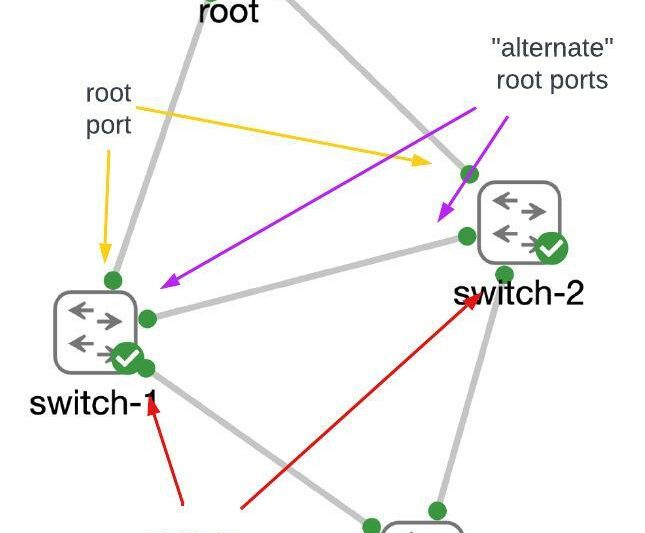
Note: The root bridge in a network has NO root ports as it is the root of the tree. Therefore ALL PORTS of the root bridge should have root guard enabled.
Now we’ll go ahead and enable root guard on interface Gig0/0 on both switch-1 and switch-2.
switch-1(config)#interface gigabitEthernet 0/0
switch-1(config-if)#spanning-tree guard root

*Oct 13 15:06:28.893: %SPANTREE-2-ROOTGUARD_CONFIG_CHANGE: Root guard enabled on port GigabitEthernet0/0.
*Oct 13 15:06:28.909: %SPANTREE-2-ROOTGUARD_BLOCK: Root guard blocking port GigabitEthernet0/0 on VLAN0001.
And look at that. As soon as it is enabled, we see syslog messages indicating that root guard has begun blocking the port. If we check the status of spanning tree on switch-1 we can verify that the root of the spanning tree has returned to the correct root switch.
switch-1#show span

VLAN0001
  Spanning tree enabled protocol rstp
  Root ID    Priority    16385
             Address     5254.000e.dde8
             Cost        4
             Port        2 (GigabitEthernet0/1)
             Hello Time   2 sec  Max Age 20 sec  Forward Delay 15 sec

  Bridge ID  Priority    32769  (priority 32768 sys-id-ext 1)
             Address     5254.0017.ae37
             Hello Time   2 sec  Max Age 20 sec  Forward Delay 15 sec
             Aging Time  300 sec

Interface           Role Sts Cost      Prio.Nbr Type
------------------- ---- --- --------- -------- --------------------------------
Gi0/0               Desg BKN*4         128.1    P2p *ROOT_Inc
Gi0/1               Root FWD 4         128.2    P2p
Gi0/2               Desg LRN 4         128.3    P2p
Gi0/3               Altn BLK 4         128.4    P2p
There’s one other command that is handy to know when troubleshooting spanning-tree ports that aren’t behaving as expected:
switch-1#show spanning-tree inconsistentports

Name                 Interface                Inconsistency
-------------------- ------------------------ ------------------
VLAN0001             GigabitEthernet0/0       Root Inconsistent

Number of inconsistent ports (segments) in the system : 1
Take the scare out of spooky spanning tree with knowledge
Hopefully, this post helps to lower your heart rate a little the next time you think about making changes to the network that might impact your spanning-tree network. But I also hope it shows you, as a network engineer, the importance of recalling the fundamental skills and knowledge you have learned as you move onward to more specialized areas of networking. I was definitely kicking myself when I realized that I had completely overlooked ensuring that our spanning-tree network was well-designed and protected from unexpected or unintended changes.
While no one wants to have a network outage or even a minor disruption, they will happen. What is important, is that we learn from them. And we become better network engineers for them.
Do you have a spooky network ghost story from your own work as a network engineer? Ever had a scary encounter with a network outage or problem that helped you learn a lesson you’ll never forget? Share them in the comments. Trick or treat!
Some handy links for digging deeper into spanning tree:
If you’d like to dive deeper into this topic, I pulled a few links together for you.
- Understanding spanning-tree and how it works is part of the CCNA blueprint. The “Implementing and Administering Cisco Solutions (CCNA) v1.0” course is a great resource to get started.
- And knowing how to implement spanning-tree is part of the Enterprise Core blueprint and is covered in the “Implementing and Operating Cisco Enterprise Network Core Technologies (ENCOR) v1.2” course.
- The root guard feature has been available in Cisco software for a very long time. This tech note discusses it and provides a great description.
- I found this post over on the Cisco Learning Network that discusses many of the spanning-tree features that should be part of every network design.
Join the Cisco Learning Network today for free.
Follow Cisco Learning & Certifications
Twitter | Facebook | LinkedIn | Instagram
Use #CiscoCert to join the conversation.


Excelente nivel técnico.
Muy bueno el blog.
Gracias por leer. Me alegra que lo disfrutaras.
Interesting
Excelente información la que tiene este blog
Spanning-Tree siempre será importante y relevante 😀
Excellent information that was shared. Thank you
You are welcome! Thanks for reading.
Agreed
Very good
Thank you! I’m glad you found it useful and interesting.
Great illustration!
The best examples come from real life experiences. Every network engineer has one or two spanning-tree stories.
Humor and knowledge, excellent info
I always find I learn better when I’ve got a smile on my face.
It’s good to know even the most experienced engineer could have these kind of problems
Oh yea… doesn’t matter the amount of experience you have. The experience is very helpful in identifying and resolving problems when they occur.
This is a great way to present quite a dry topic like spanning tree.
Thank you! Tying a concept back to real world designs and engineering always help me see the reason for things that might seem purely theoretical when learning.
Thanks Hank, this kind of thing is always worth revising!!
Absolutely! Much of what a network engineer learns at the start of their training remains relevant forever. Brushing up on the fundamentals is always valuable.
Good article, thank you!
You are welcome!
Network refresh at a remote office, everything seems to go smoothly. Next day site keeps going up and down, PC’s and phones work and then they all quit working. 3 days of troubleshooting and we find out that the smart hands local technician had assigned the default gateway as the IP address of the network connected UPS.
Oh man, duplicate IP issues are no joke. Another classic issue that will happen again and again. I recently had a duplicate MAC address causing issues on our network. Maybe worth another blog…
Excellent visuals and explanation! I love it!
Thank you! I always try to figure out how to add pictures and code/command examples in posts that help drill into the key concepts. I’m glad you found them useful.
Very good article!!
Thank you so much!
I forgot how scary spanning-tree could be. Thanks for the Halloween fright! LOL!
Next year I’ll put a post together about my MOST scary networking topic – changing AAA configuration on a network device 😱
Nice config example
Thanks! The configuration of many features are straightforward. We just must remember to use them.
Excellent Explanaition , thanks!
You are welcome! Thanks for stopping by and reading.
Sometimes it is a lot of fun, thank you for bringing up such an important topic.
Networking is always fun… well not in the middle of an outage when everyone is looking at you I suppose. But when you fix something, that part feels great.
What a outstanding article. The information is so appreciated!
You are too kind! Definitely stop back for more information.
Love all the content Hank provides to the community. Been in very similar situations in the past with spanning tree. It’s no fun!
Aw, thanks Brad. I’m love the community and sharing stories with you all.
Hey Hank, this is a great highlight of those little features that help with stability on a network.
Agreed. What is another similar feature that you like using?
Great read! some of the symptoms reporting in the article are exactly what is happening randomly in a network I am on. Going to look at spanning tree tomorrow and ensure it is not the cause of the random/intermittent issues!
Excellent! Even if it isn’t spanning-tree, I hope you find the answer soon.
Good Article, thanks!
Thanks for the insightful blog
Insightful
Nice summary for one of the basics in networking.
Good sharing,
Great blog .. either you know STP or it bring your network down .
Forward Learning
Well explained.
Excellent information shared . i would like to SEE more of that
Excellent!
Excellent content, thanks for sharing!@
Good article, thank you!
Excellent story and lesson! I have always thought it was good to review past blogs, videos and other material that I had studied in my certification journey. Sometimes you can set things up and forget them when there is no issue. I was once reconfiguring VLANs on a switch in a lab using router on a stick. Every time I assigned the VLAN an IP and performed a shut/no shut, I discovered the previous VLAN went to administratively down. I hadn’t done this in a while, so I searched for some details and reviewed a video and suddenly realized I was unnecessarily assigning an IP to a VLAN on a layer 2 switch! DUH! It goes to show that periodically reviewing things to keep them fresh in your mind pays off!
Excelente STP es dificil de aprender aunque se ve facil.
Thanks for the awesome content!
Thank you for the information.
Great to read stories from the trenches. Another lesson learned, don’t let friends NAT to a firewall interface participating in dynamic routing…it doesn’t end well.
Buenisima información. Gracias por compartir
Hey this kind of posts are very useful, thank you !
Excelente explicación,
Gracias por compartir
Thank you, nice reminder.
Flapping ports. Happy Halloween.
Thanks for the inside
Great information! Very useful.
Thank you.
Good explaination of STP
At the first glance STO looks simple and a no brainer, but I have witnessed many issues from it in a large scale network, so you need be careful with it
Thanks for sharing. Encountering issues like this can be a hard way to learn but gives you valuable experience that you won’t readily forget.
Thank you for sharing your experience with us about spanning tree 🙂
Saved this post to my Bookmarks. Excelente explanation
Very very interesting
Thanks for sharing.
I remember when everyone was afraid of spanning-tree. Good thing Cisco kicked in the door and showed the way.
Thank you for sharing
Thanks Hank, this is a handy post. L2 in general is often overlooked/forgotten, but especially STP. I’m guilty myself and often have to do a quick refresh on STP topics when they come up. Best practices and build procedures are the way to go; STP priorities should be explicitly configured plus features such as root guard, portfast, bpdu guard, bpdu filter, etc. should be used where appropriate; they were created for a reason!
Great refresher!
Always good to revisit these technical concepts. Thanks for a good read, Hank!
One of the guys configured the uplink with on instead of active, while debugging I disabled suspend individual and caused the loop in the core.
Good anecdote to exemplify that one should remember the fundamentals.
Excellent blog very informative and very interesting concepts
Thank you, real world scenarios always help to better understand the material.
I remember people who used to disable that spooky spanning tree feature on their networks because they were terrified of ‘spanning tree loops’.
Thanks for sharing your experience with detailed explanation which gave me the better understanding about STP protocol in real situation.
Excellent
Lovely story and so well presented. Thank you!
A succinct explanation of spanning tree. We tend to forget the fundamentals/basics as we advance. Sometimes incidents are what solidify the knowledge especially in stable networks.
Reviewed