Background
Network Plug-and-Play allows switches, routers, and wireless access points to be on-boarded to the network. An agent in the device, connects to Cisco DNA center and downloads the required software and device configuration.
In order for this to be truly zero-touch, a network connection is needed. For AP and routers, the initial network connections are reasonably simple. With switches, there a few more options – with vlan, trunking, and port channel options.
I get a lot of questions about the different options and will document the most common ones.
Plug and Play
I am going to assume you are familiar with PnP, and know there is an initial discovery phase, where the device discovers Cisco DNA Center, then a configuration template can be pushed down to the device. All communication is from the device to Cisco DNA Center, which means the source IP address can change on the PnP device. This is significant if you want to change from a DHCP address to static, or even change the IP address/interface that are used for management.
Use Case 1: Trunk Interface, Vlan 1 management, Single Link
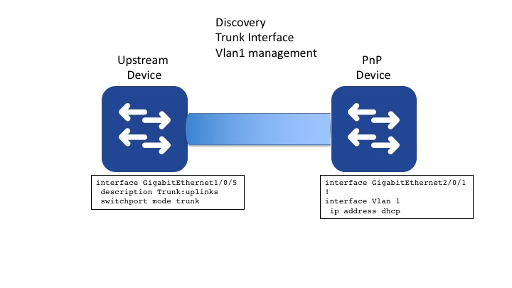
This is the simplest use case. It requires DHCP on vlan 1 on the upstream switch. There is nothing really required here. When the PnP switch boots, all interfaces are running Dynamic Trunking Protocol, so a trunk is automatically established. Vlan 1 will have dhcp enabled.
Looking at the trunk status on the pnp device, trunking has been established and vlan 1 is active.
switch#show int g2/0/1 trunk

Port        Mode             Encapsulation  Status        Native vlan
Gi2/0/1     auto             802.1q         trunking      1

Port        Vlans allowed on trunk
Gi2/0/1     1-4094

Port        Vlans allowed and active in management domain
Gi2/0/1     1

Port        Vlans in spanning tree forwarding state and not pruned
Gi2/0/1     1
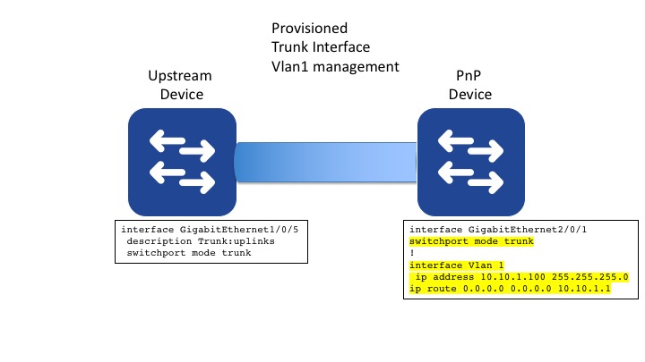
The configuration will push a static IP address for vlan 1. Because the dhcp address is changed to static ip, a default route needs to be added. The uplink is being hard coded as a trunk, but this is optional. I have not included any credentials in the configuration as this is done automatically as part of the provisioning.
hostname 3k-stack
int vlan 1
ip address 10.10.1.100 255.255.255.0
ip route 0.0.0.0 0.0.0.0 10.10.1.1

int g2/0/1
switchport mode trunk
The final switch configuration will be as follows:
Use Case 2: Trunk interface, Vlan 15 management, single link
In this case, I want to use vlan15 for management, instead of vlan1. (this could be any vlan number, I just chose 15). This can be achieved in two ways:
- I could switchover to vlan 15 in my template
- I can use the pnp startup-vlan command in the upstream switch to cause the pnp switch to create vlan 15.
The second case is really useful as it simplifies the deployment. Once I add the “pnp startup-vlan 15” command, any pnp switch will have vlan 15 created and the uplink converted to a trunk with vlan 15 enabled. This process uses CDP under the covers to communicate to the PnP device, and a process on the device creates the vlan and enables DHCP.
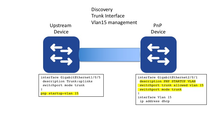
Looking at the state of the uplink, you can see the vlan 15 is active on the trunk.
Switch#show int g2/0/1 trunk

Port        Mode             Encapsulation  Status        Native vlan
Gi2/0/1     on               802.1q         trunking      1

Port        Vlans allowed on trunk
Gi2/0/1     15

Port        Vlans allowed and active in management domain
Gi2/0/1     15

Port        Vlans in spanning tree forwarding state and not pruned
Gi2/0/1     15
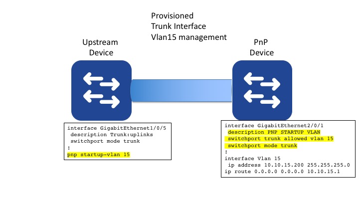
I can then push a configuration to convert the dhcp IP address to static IP.
int vlan 15
ip address 10.10.15.200 255.255.255.0
ip route 0.0.0.0 0.0.0.0 10.10.15.1
Use Case 3: Trunk interface, Vlan 15 management, link aggregation
In this case, there are two links in a bundle. This has been configured in the upstream switch. The same process that creates the management vlan 15, will also create an etherchannel on the PnP device. Only one interface will be added to the bundle.
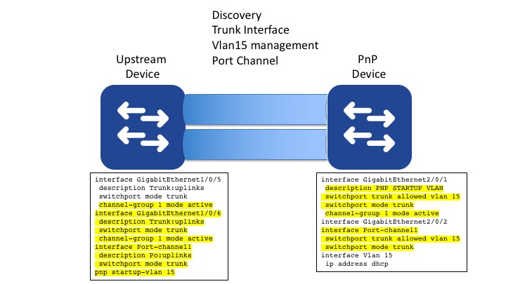
The port channel contains a single member.
switch#show int g2/0/1 ether
Port state    = Up Mstr Assoc In-Bndl
Channel group = 1           Mode = Active          Gcchange = -
Port-channel  = Po1         GC   =   -             Pseudo port-channel = Po1
Port index    = 0           Load = 0x00            Protocol =   LACP

Flags:  S - Device is sending Slow LACPDUs   F - Device is sending fast LACPDUs.
        A - Device is in active mode.        P - Device is in passive mode.

Local information:
                            LACP port     Admin     Oper    Port        Port
Port      Flags   State     Priority      Key       Key     Number      State
Gi2/0/1   SA      bndl      32768         0x1       0x1     0x202       0x3D

 Partner's information:

                  LACP port                        Admin  Oper   Port    Port
Port      Flags   Priority  Dev ID          Age    key    Key    Number  State
Gi2/0/1   SA      32768     7c95.f3bd.2a00   4s    0x0    0x1    0x106   0x3D

Age of the port in the current state: 0d:00h:01m:57s
In this case, all I need to do is configure the other port into the bundle.
int vlan 15
ip address 10.10.15.200 255.255.255.0
ip route 0.0.0.0 0.0.0.0 10.10.15.1
int g2/0/2
switchport trunk allowed vlan 15
 switchport mode trunk
 channel-group 1 mode active
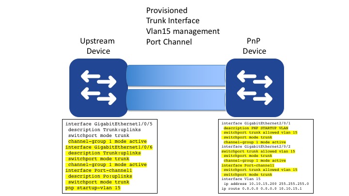
Then the two ports will be in a bundle.
show int port-channel 1 etherchannel
Port-channel1   (Primary aggregator)

Age of the Port-channel   = 0d:00h:09m:06s
Logical slot/port   = 12/1          Number of ports = 2
HotStandBy port = null
Port state          = Port-channel Ag-Inuse
Protocol            =   LACP
Port security       = Disabled

Ports in the Port-channel:

Index   Load   Port     EC state        No of bits
------+------+------+------------------+-----------
  0     00     Gi2/0/1  Active             0
  0     00     Gi2/0/2  Active             0

Time since last port bundled:    0d:00h:01m:49s    Gi2/0/2
Time since last port Un-bundled: 0d:00h:09m:03s    Gi2/0/1
Management interface switchover
It is also possible to do discovery and deployment via the management interface. On a cat 9k with will be Gig0/0. This interface is in a different VRF, so you need to take that into account. The communication back to DNAC will be via this interface, as will the discovery that takes place one the device is provisioned. If you change over to inband management, you need to change the ‘ip http client source-interface’ command to reflect the new interface. This could be a loopback, or an SVI.
Remember if you switch the source interface, it needs to have a route back to DNAC. This is also the IP address that will be used to add the device to the inventory.
USB bootstrap
The other challenge you may have is no access to DHCP. In this case ISR routers and 9k switches support a USB bootstrap. You can place a configuration file called ‘ciscortr.cfg’ on the root of a usb drive and the switch will execute those commands when it boots. This file needs to contain a way to get ip connectivity and the pnp profile for the device to connect to DNAC. Then the normal PnP process will take over.
vlan 15
int vlan 15
ip address 10.10.15.200 255.255.255.0
ip route 0.0.0.0 0.0.0.0 10.10.15.1
no shut
pnp profile BOOTSTRAP
transport http ipv4 10.10.10.181 port 80
What next?
There are a number of other blogs in this series on PnP with Cisco DNA Center. You can find them here.
In the meantime, if you would like to learn more about Cisco DNA Center, you could visit Cisco DevNet. DevNet has further explanations about other Cisco DNA Center topics.
Thanks for reading.
@adamradford123
We’d love to hear what you think. Ask a question or leave a comment below.
And stay connected with Cisco DevNet on social!
Twitter @CiscoDevNet | Facebook | LinkedIn
Visit the new Developer Video Channel