
Part 1 and Part 2 of this blog series covered native cloud networking and firewall rules automation on GCP, and a read through is recommended for completeness. This final post of the series is about enabling external access for cloud resources. More specifically, it will focus on how customers can enable external connectivity from and to GCP, using either Cloud Native Router or Cisco Cloud Router (CCR) based on Cisco Catalyst 8000v, depending on use case.
By expanding previous capabilities, Cisco Cloud Network Controller (CNC) will provision routing, automate VPC peering between infra and user VPCs, and BGP IPSec connectivity to external networks with only a few steps using the same policy model.
Scenario
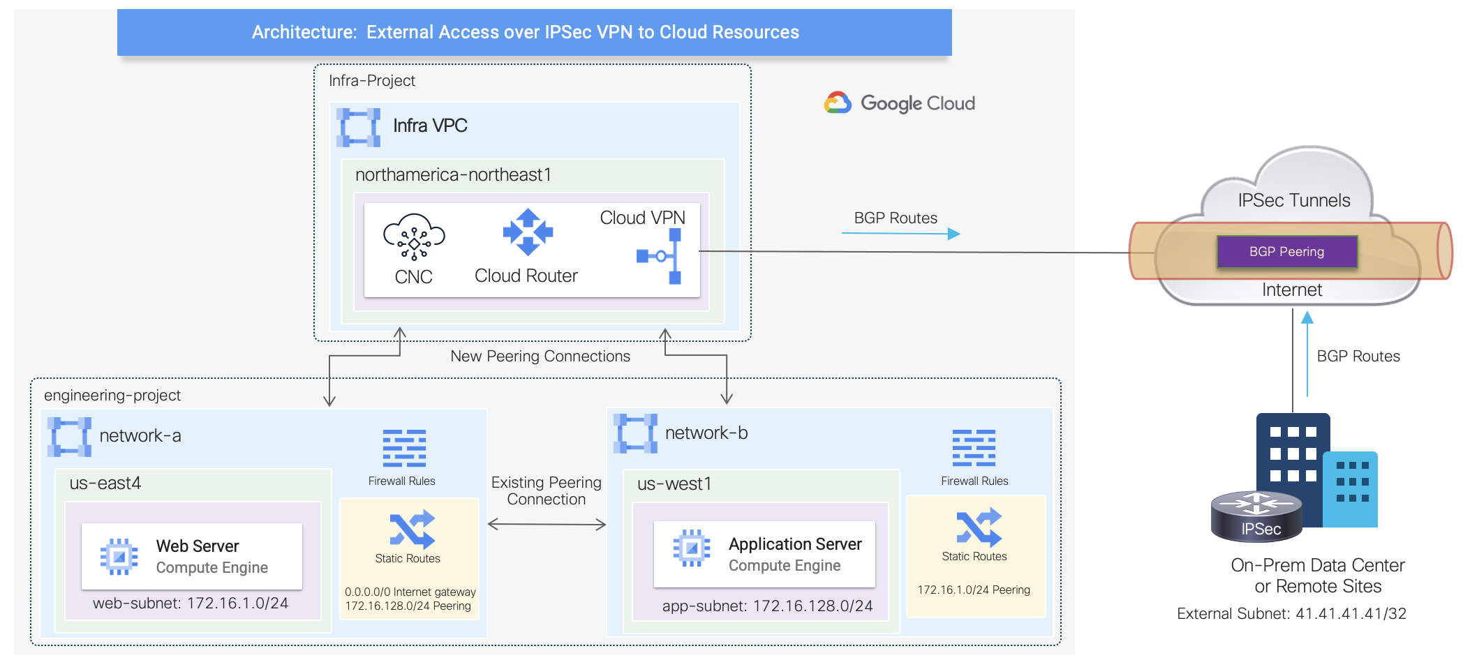
This scenario will leverage the existing configuration built previously represented by network-a and network-b VPCs. These user VPCs will be peered with the infra VPC in a hub and spoke architecture, where GCP cloud native routers will be provisioned to establish BGP IPSec tunnels with an external IPSec device. The GCP cloud native routers are composed by the combination of a Cloud Router and a High-availability (HA) Cloud VPN gateway.
The high-level topology below illustrates the additional connections automated by Cisco CNC.
Provisioning Cloud Native Routers
The first step is to enable external connectivity under Region Management by selecting in which region cloud native routers will be deployed. For this scenario, they will be provisioned in the same region as the Cisco CNC as depicted on the high-level topology. Additionally, default values will be used for the IPSec Tunnel Subnet Pool and BGP AS under the Hub Network representing the GCP Cloud Router.
The cloud native routers are being provisioned purposely on a different region to illustrate the ability of having a dedicated hub network with external access. However, they could have been deployed on the same region as the user VPCs.
Note: a brief overview of the Cisco CNC GUI was provided on Part 1.
Enabling External Networks
The next step is to create an External Network construct within the infra tenant. This is where an external VRF is also defined to represent external networks connected to on-premises data centers or remote sites. Any cloud VRF mapped to existing VPC networks can leak routes to this external VRF or can get routes from it. In addition to the external VRF definition, this is also where VPN settings are entered with the remote IPSec peer details.
The configuration below illustrates the stitching of the external VRF and the VPN network within the region where the cloud native routers are being provisioned in the backend. For simplicity, the VRF was named as “external-vrf” but in a production environment, the name should be defined wisely and aligned to the external network as to improve operations.
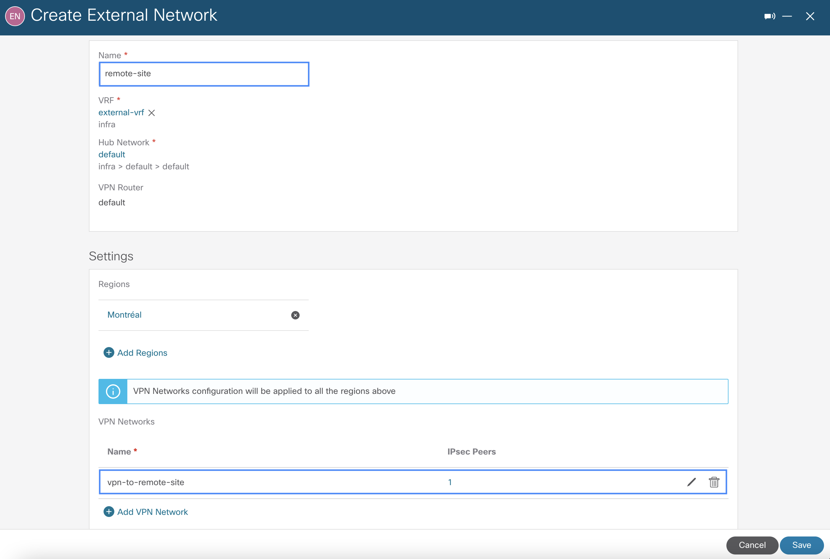
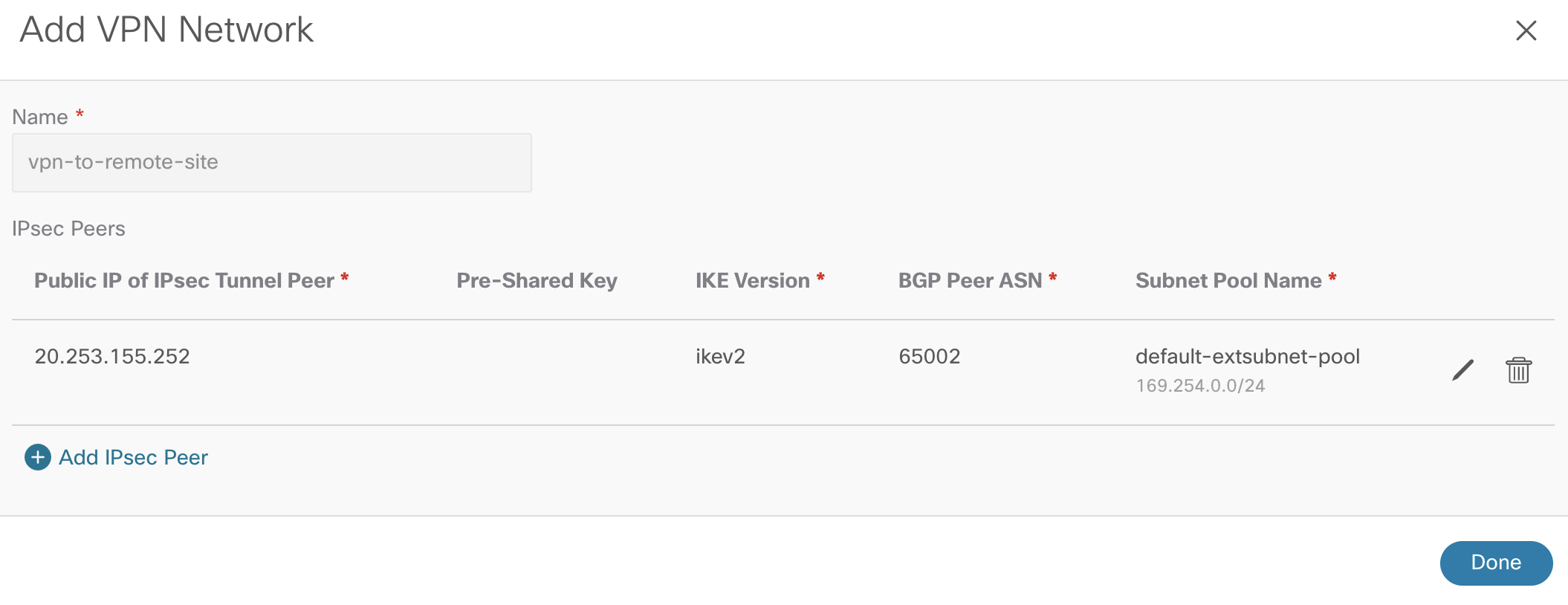
The VPN network settings require public IP of the remote IPSec device, IKE version, and BGP AS. As indicated earlier, the default subnet pool is being used.
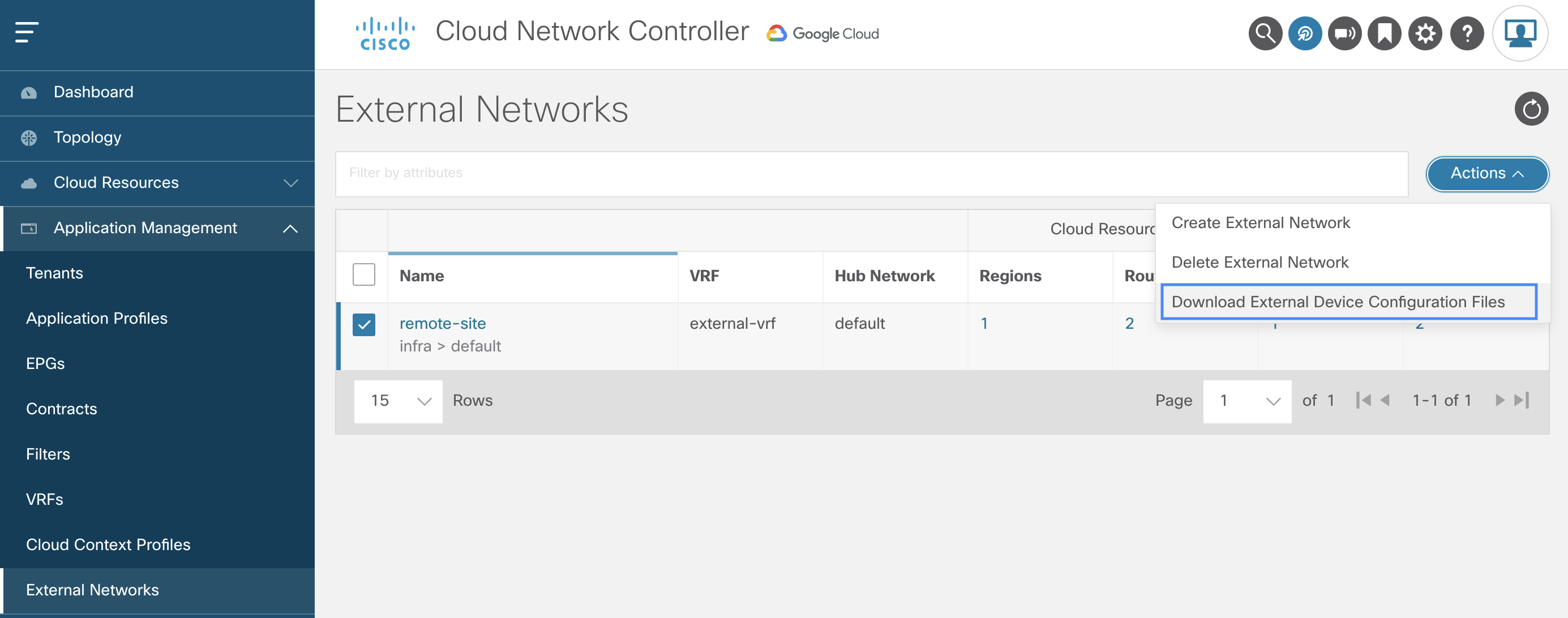
 Once the external network is created, Cisco CNC generates a configuration file for the remote IPSec device to establish BGP peering and IPSec tunnels with the GCP cloud native routers. Below is the option to download the configuration file.
Configuring External IPSec Device
As the configuration file provides most of the configuration required for the external IPSec device, customization is needed only on tunnel source interface and routing settings where applicable to match local network requirements. In this example, the remote IPSec device is a virtual router using interface GigabitEthernet1. For brevity, only one of the IPSec tunnels config is shown below along with all the other config generated by Cisco CNC.
vrf definition external-vrf
    rd 100:1
    address-family ipv4
    exit-address-family

interface Loopback0
    vrf forwarding external-vrf
    ip address 41.41.41.41 255.255.255.255

crypto ikev2 proposal ikev2-1
    encryption aes-cbc-256 aes-cbc-192 aes-cbc-128
    integrity sha512 sha384 sha256 sha1
    group 24 21 20 19 16 15 14 2

crypto ikev2 policy ikev2-1
    proposal ikev2-1

crypto ikev2 keyring keyring-ifc-3
    peer peer-ikev2-keyring
        address 34.124.13.142
        pre-shared-key 49642299083152372839266840799663038731

crypto ikev2 profile ikev-profile-ifc-3
    match address local interface GigabitEthernet1
    match identity remote address 34.124.13.142 255.255.255.255
    identity local address 20.253.155.252
    authentication remote pre-share
    authentication local pre-share
    keyring local keyring-ifc-3
    lifetime 3600
    dpd 10 5 periodic

crypto ipsec transform-set ikev-transport-ifc-3 esp-gcm 256
    mode tunnel

crypto ipsec profile ikev-profile-ifc-3
    set transform-set ikev-transport-ifc-3
    set pfs group14
    set ikev2-profile ikev-profile-ifc-3

interface Tunnel300
    vrf forwarding external-vrf
    ip address 169.254.0.2 255.255.255.252
    ip mtu 1400
    ip tcp adjust-mss 1400
    tunnel source GigabitEthernet1
    tunnel mode ipsec ipv4
    tunnel destination 34.124.13.142
    tunnel protection ipsec profile ikev-profile-ifc-3

ip route 34.124.13.142 255.255.255.255 GigabitEthernet1 192.168.0.1

router bgp 65002
    bgp router-id 100
   bgp log-neighbor-changes
    address-family ipv4 vrf external-vrf
        network 41.41.41.41 mask 255.255.255.255
        neighbor 169.254.0.1 remote-as 65534
        neighbor 169.254.0.1 ebgp-multihop 255
        neighbor 169.254.0.1 activate
Verifying External Connectivity status
Once configuration is applied, there are a few ways to verify BGP peering and IPSec tunnels between GCP and external devices: via CLI on the IPSec device itself and via Cisco CNC GUI on the External Connectivity dashboard.
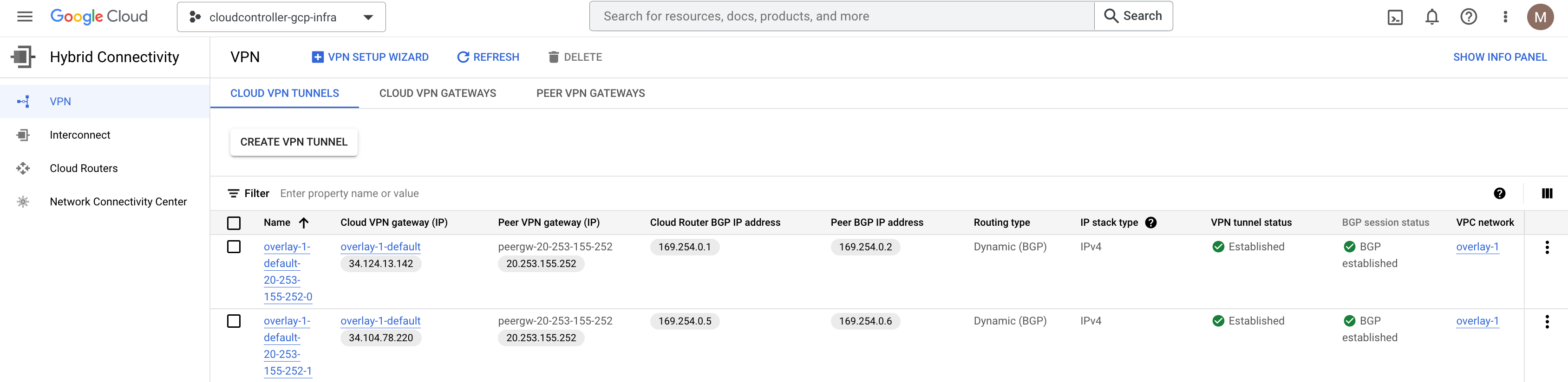
In the GCP console (infra project), under Hybrid Connectivity, it shows both the IPSec and BGP sessions are established accordingly by the combination of a Cloud Router and an HA Cloud VPN gateway automated by Cisco CNC, upon definition of the External Network. Note that the infra VPC network is named as overlay-1 by default as part of the Cisco CNC deployment from the marketplace.
Route Leaking Between External and VPC Networks
Now that BGP IPSec tunnels are established, let’s configure inter-VRF routing between external networks and existing user VPC networks from previous sections. This works by enabling VPC peering between the user VPCs and the infra VPC hosting VPN connections, which will share these VPN connections to external sites. Routes received on the VPN connections are leaked to user VPCs, and user VPC routes are advertised on the VPN connections.
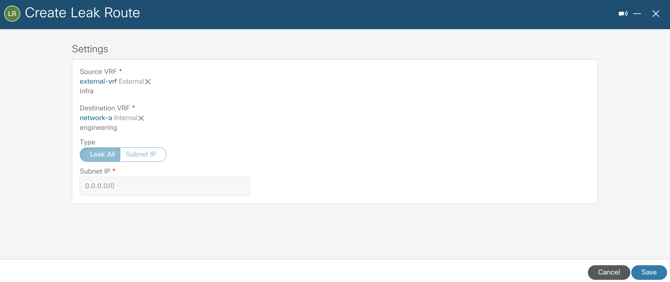
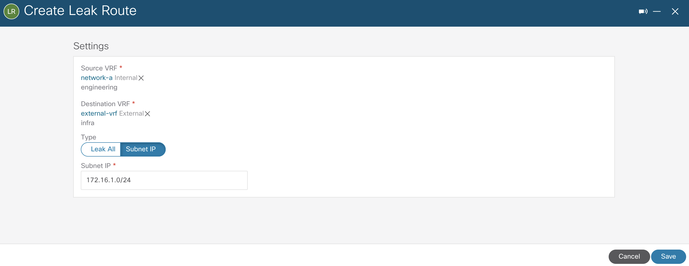
Using inter-VRF routing, the route is leaked between the external VRF of the VPN connections and the cloud local user VRFs. The configuration below illustrates route leaking from external-vrf to network-a.
The reverse route leaking configuration from network-a to external-vrf is filtered with Subnet IP to show granularity. Also, the same steps were performed for network-b but not depicted for brevity.
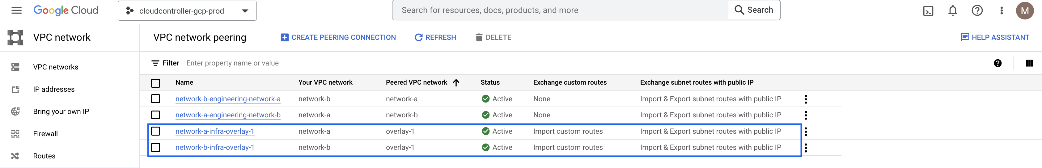
In addition to the existing peering between network-a and network-b VPCs, now both user VPCs are also peered with the infra VPC (overlay-1) as depicted on the high-level topology.
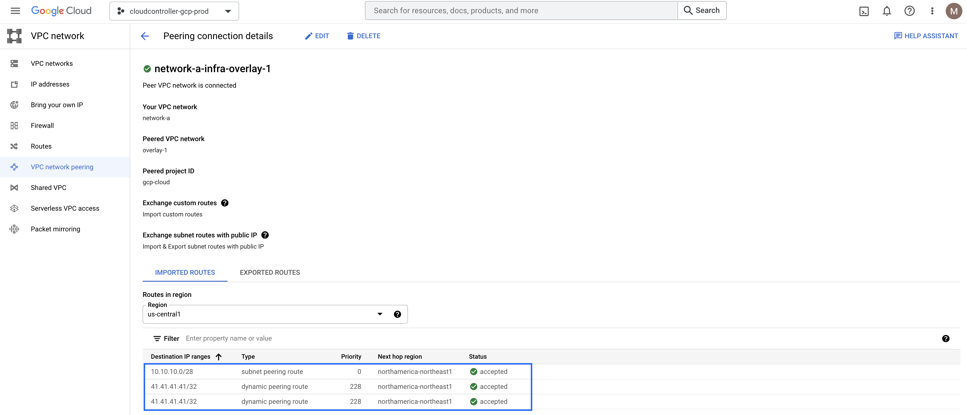
By exploring one of the peering connection details, it is possible to see the external subnet 41.41.41.41/32 in the imported routes table.
On the remote IPSec device, the subnets from network-a and network-b VPCs are learned over BGP peering as expected.
remote-site#sh bgp vpnv4 unicast vrf external-vrf
<<<output omitted for brevity>>>
     Network          Next Hop            Metric LocPrf Weight Path
Route Distinguisher: 100:1 (default for vrf external-vrf)
 *>   41.41.41.41/32   0.0.0.0                  0         32768 i
 *    172.16.1.0/24    169.254.0.5            100             0 65534 ?
 *>                    169.254.0.1            100             0 65534 ?
 *    172.16.128.0/24  169.254.0.5            100             0 65534 ?
 *>                    169.254.0.1            100             0 65534 ?
remote-site#
Defining External EPG for the External Network
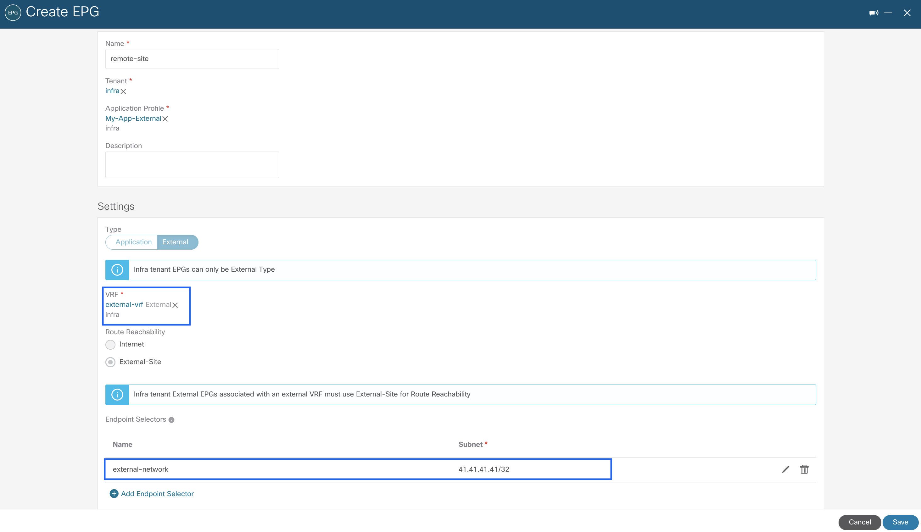
Up to this point, all routing policies were automated by Cisco CNC to allow external connectivity to and from GCP. However, firewall rules are also required for end-to-end connectivity. This is accomplished by creating an external EPG using subnet selection as the endpoint selector to represent external networks. Note that this external EPG is also created within the infra tenant and associated to the external-vrf created previously.
The next step is to apply contracts between the external EPG and the previously created cloud EPGs to allow communication between endpoints in GCP and external networks, which in this scenario is represented by 41.41.41.41/32 (loopback0 on remote IPSec device). As this is happening across different tenants, the contract scope is set to global and exported from the engineering tenant to the infra tenant and vice-versa, if allowing traffic to be initiated from both sides.

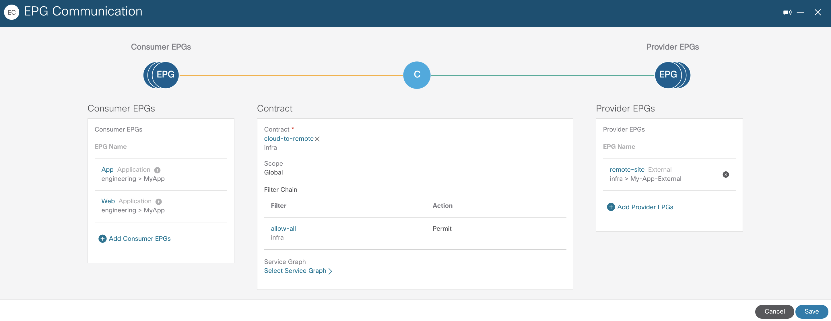
On the backend, the combination of contracts and filters translates into proper GCP firewall rules, as covered in details on Part 2 of this series. For brevity, only the outcome is provided below.
remote-site#ping vrf external-vrf 172.16.1.2 source lo0
Type escape sequence to abort.
Sending 5, 100-byte ICMP Echos to 172.16.1.2, timeout is 2 seconds:
Packet sent with a source address of 41.41.41.41 !!!!!
Success rate is 100 percent (5/5), round-trip min/avg/max = 84/84/86 ms
remote-site#ping vrf external-vrf 172.16.128.2 source lo0
Type escape sequence to abort.
Sending 5, 100-byte ICMP Echos to 172.16.128.2, timeout is 2 seconds:
Packet sent with a source address of 41.41.41.41 !!!!!
Success rate is 100 percent (5/5), round-trip min/avg/max = 132/133/138 ms
root@web-server:/home/marinfer# ping 41.41.41.41
PING 41.41.41.41 (41.41.41.41) 56(84) bytes of data.
64 bytes from 41.41.41.41: icmp_seq=1 ttl=254 time=87.0 ms
64 bytes from 41.41.41.41: icmp_seq=2 ttl=254 time=84.9 ms
64 bytes from 41.41.41.41: icmp_seq=3 ttl=254 time=83.7 ms
64 bytes from 41.41.41.41: icmp_seq=4 ttl=254 time=83.8 ms
root@web-server:/home/marinfer#

root@app-server:/home/marinfer# ping 41.41.41.41
PING 41.41.41.41 (41.41.41.41) 56(84) bytes of data.
64 bytes from 41.41.41.41: icmp_seq=1 ttl=254 time=134 ms
64 bytes from 41.41.41.41: icmp_seq=2 ttl=254 time=132 ms
64 bytes from 41.41.41.41: icmp_seq=3 ttl=254 time=131 ms
64 bytes from 41.41.41.41: icmp_seq=4 ttl=254 time=136 ms
root@app-server:/home/marinfer#
Advanced Routing Capabilities with Cisco Cloud Router
Leveraging native routing capabilities as demonstrated may suffice for some specific use cases and be limited for others. Therefore, for more advanced routing capabilities, Cisco Cloud Routers can be deployed instead. The provisioning process is relatively the same with CCRs also instantiated within the infra VPC in a hub and spoke architecture. Besides having the ability to manage the complete lifecycle of the CCRs from the Cisco CNC, customers can also choose different tier-based throughput options based on requirements.
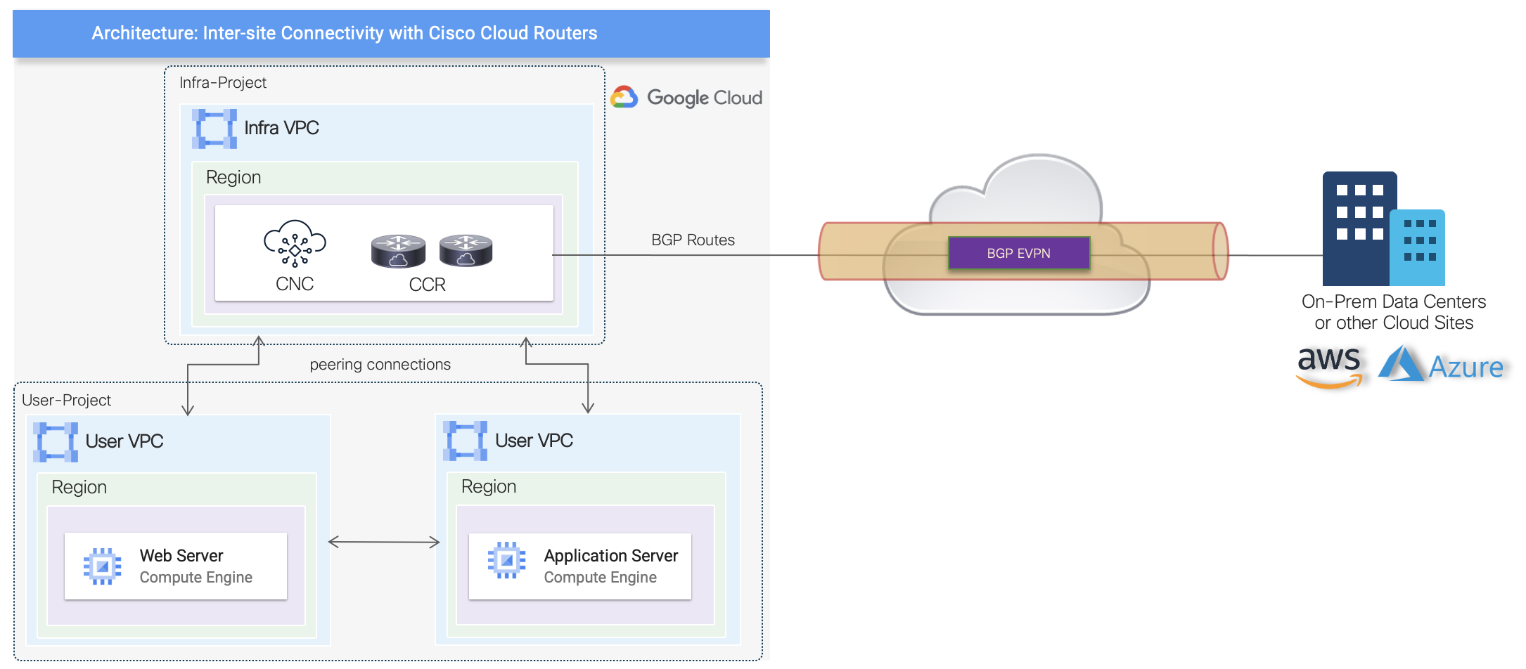
One of the main use cases for leveraging Cisco Cloud Routers is the BGP EVPN support across different cloud sites running Cisco CNC, or for hybrid cloud connectivity with on-prem sites when policy extension is desirable. The different inter-site uses cases are being documented on specific white papers, and below is a high-level topology illustrating the architecture.
Summary
There are multiple ways of enabling external access and hybrid cloud connectivity for cloud resources. Cisco CNC provides flexibility to customers by giving options to leverage native routing capabilities or more advanced features with CCR. Additionally, although not covered as part of this series, ability to import and manage connectivity to brownfield VPCs is also supported to address use cases with existing VPC networks.
In conclusion, this blog series introduces Cisco CNC for customers to explore and understand the benefits of leveraging a cloud networking software to automate and build their cloud environments on GCP. Moreover, Cisco CNC makes it easy to integrate with existing cloud automation tools such as Terraform by publishing continuous provider updates.
Resources
Guides
Cisco Cloud Network Controller for Google Cloud Installation Guides
Cisco Cloud Network Controller for Google Cloud User Guides
Blog Series: Introducing Cisco Cloud Network Controller on Google Cloud Platform
Part 1: Native Cloud Networking Automation
Part 2: Contract-based Routing and Firewall Rules Automation


