Written by Vasanta Rao, Technical Marketing Engineer, Cisco Transceiver Modules Group
In a Part 2 of this series of posts, Priya described the two main types of optical fiber: single-mode and multi-mode. Now we look deeper into limitations of high-speed networks, when optical data propagates through the fiber from transmitter to receiver. We focus on fiber dispersion.
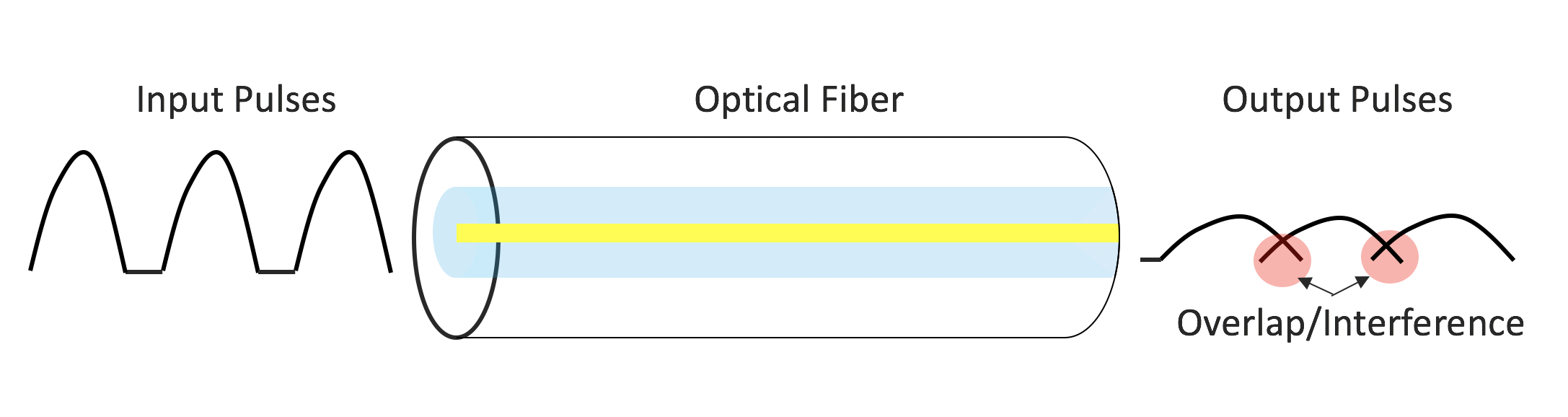
Optical data signals are comprised of very short bursts of light, or optical pulses. When we transmit optical pulses through fiber, they broaden. This means that they become longer in duration as they travel through the fiber. If the fiber is long enough, this broadening causes the pulses to overlap and interfere with each other, which impacts the receiver’s ability to resolve the transmitted data, resulting in bit errors. This pulse broadening is due to a phenomenon called dispersion and limits the transmission bandwidth and distance. Single-mode and multi-mode fiber are each dominated by different types of dispersion.
Modal Dispersion
Since multi-mode fiber has a large core diameter, it can guide many different spatial modes of light. The different modes enter the fiber and reflect off the cladding wall at different angles, which means they travel different distances, and therefore propagate down the fiber at different speeds. Because they exit the fiber at different times, the optical pulses broaden. This is called modal dispersion.

Single-mode fiber is not affected by modal dispersion since it supports only one mode. However it is affected by material dispersion. There are two dispersion effects specific to single mode fiber that cause the light pulses to spread out. These are chromatic dispersion and polarization mode dispersion (PMD).
Chromatic Dispersion
In the real world a light source is never purely monochromatic (single wavelength). Instead, it is composed of different wavelengths at varying intensities near the center wavelength, such as 1310nm or 1550 nm. This is especially true for an optical pulse carrying digital information. The wavelengths experience different refractive indexes in the glass fiber, causing the shorter wavelengths to travel faster than the longer wavelengths. The optical pulse spreads out as it travels along the fiber. This dispersion is called chromatic dispersion, and is more pronounced at higher data rates.
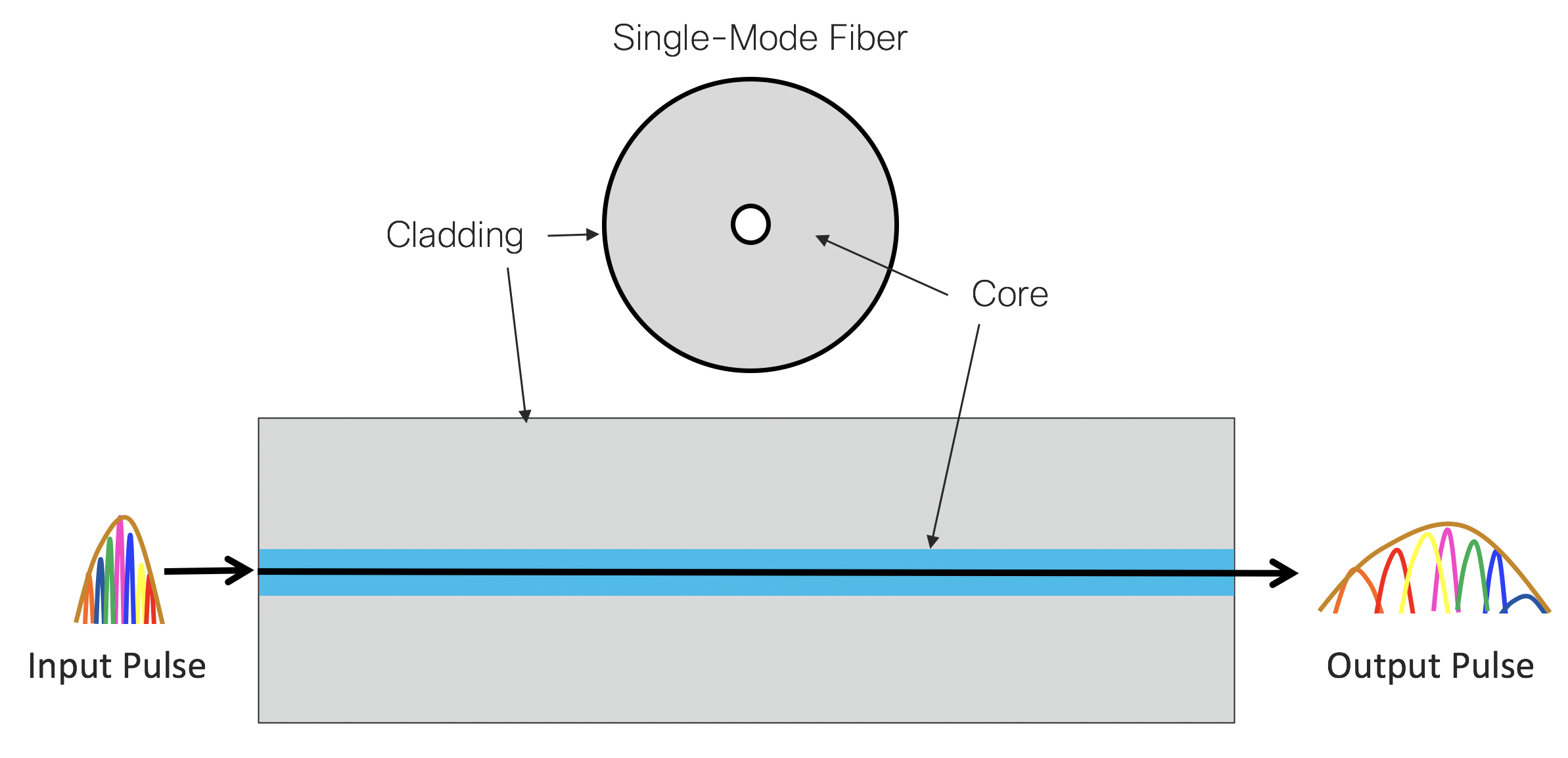
Chromatic dispersion is measured in ps/nm/km. This can be read as: For every km traveled in fiber, a pulse with 1 nm wavelength spectral width will spread by 1 ps. The amount of chromatic dispersion in optical fiber varies based on the wavelength.
An analogy would be that of a car race where the blue car arrives the finish line faster than the red car. Here, the blue wavelength travels faster than the red wavelength.

Polarization Mode Dispersion (PMD)
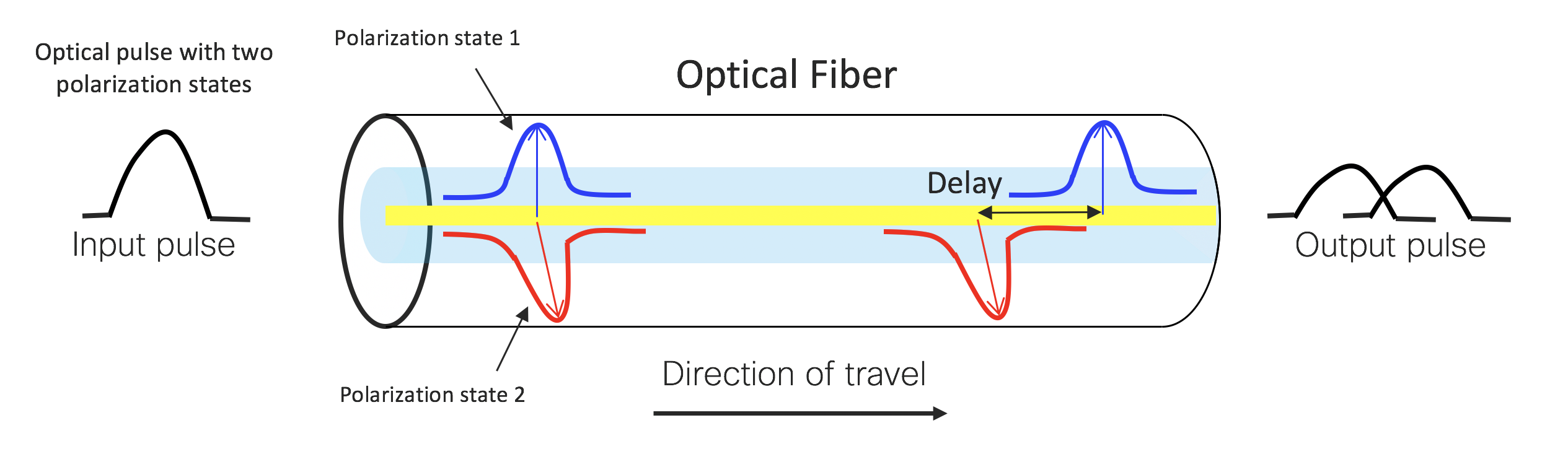
Light is an electromagnetic wave composed of a traveling electric and magnetic field. Single-mode fiber supports one propagation mode, which in turn is comprised of two orthogonal polarization modes, or states. If traveling through a perfectly cylindrical optical fiber, both polarization states would travel at exactly the same speed. However, in the real world there are stresses and manufacturing flaws in the optical fiber causing it to be non-cylindrical. These asymmetrical variations introduce small refractive index variations between the two states. Although each variation by itself is minuscule, the accumulation over tens of kilometers of fiber causes the polarization states to travel at noticeably different speeds. The light pulses then spread out in time, and have undergone polarization mode dispersion.
PMD is a random effect and is measured as an average value over time. At lower speeds like 10Gbits/s PMD is not significant. However, it does become an issue with increasing data rates at 100Gbits/s and beyond.
In our next post in this series, we will cover how to characterize and evaluate the impairments of dispersion.
For more tutorials from Cisco Optics, click here.
Subscribe to the Cisco Optics blog!
And don’t forget to watch the Cisco Optics Youtube playlist.


Pat,
Just wanted to compliment your team (Priya, Vasanta and others) on the very nicely done explanations of the fiber optics basics over the years. As an old geezer who “cut his teeth” in the fiber optics industry at Corning Glass Works in the early 1980s (when the first single mode fiber order for the MCI project came in, and turned the place upside-down), it is amazing to see how far optical fiber communications technology has come.
Looking forward to the next installment….
Sincerely,
Mike Hartmann
Mike,
Thank you for your kind remarks. I’m impressed with the team too.
By the way, I didn’t know that you took part in the historic inception of the fiber optics industry! I’m sure you must have stories from those days.
Best,
Pat