
This blog is a joint collaboration between Ravi Balakrishnan (Cisco) and Payal Singh (F5)
Applications environments have different and unique needs on how traffic is to be handled. Some applications, due to the nature of their functionality or maybe due to a business need do require that the application server(s) are able to view the real IP address of the client making the request to the application.
Now, when the request comes to the F5 BIG-IP, it has the option to change the real IP address of the request or to keep it intact. To keep it intact, the setting on the F5 BIG-IP ‘Source Address Translation’ is set to ‘None’.
As simple as it may sound to just toggle a setting on the F5 BIG-IP, a change of this setting causes significant change in traffic flow behavior.
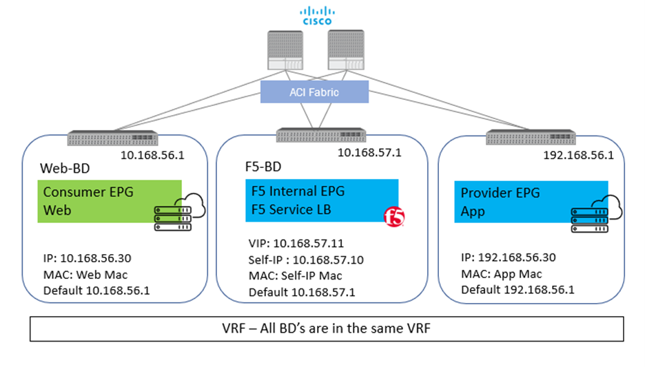
Let us take an example with some actual values. Starting with a simple setup of a standalone F5 BIG-IP with one interface on the F5 BIG-IP for all traffic (one-arm)
- Client – 10.168.56.30
- BIG-IP Virtual IP – 10.168.57.11
- BIG-IP Self IP – 10.168.57.10
- Server – 192.168.56.30
Scenario 1: With SNAT
From Client: Src: 10.168.56.30 Dest: 10.168.57.11
From BIG-IP to Server: Src: 10.168.57.10 (Self-IP) Dest: 192.168.56.30
In above scenario, the server will respond back to 10.168.57.10 and F5 BIG-IP will take care of forwarding the traffic back to the client. Here, the application server has visibility to the Self-IP 10.168.57.10 and not the client IP.
Scenario 2: No SNAT
From Client: Src: 10.168.56.30 Dest: 10.168.57.11
From BIG-IP to Server: Src: 10.168.56.30 Dest: 192.168.56.30
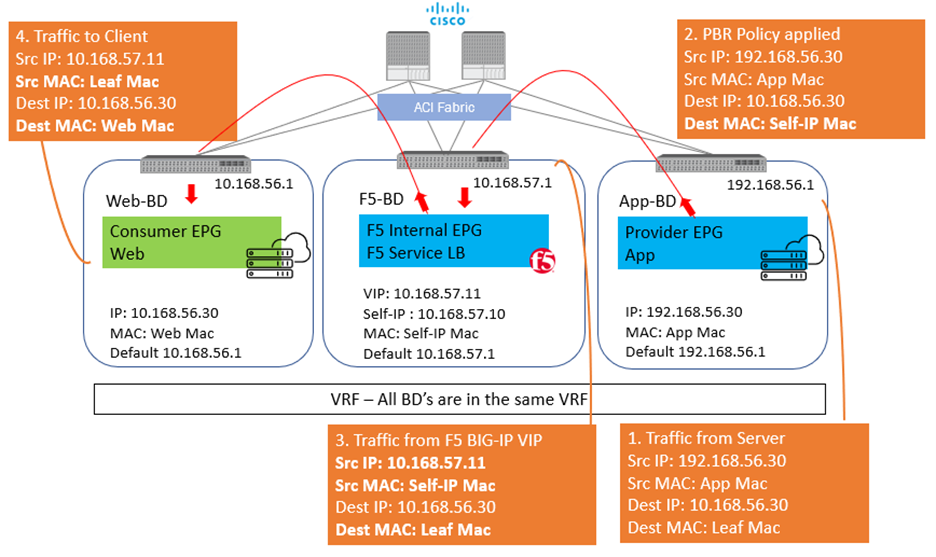
In this scenario, the server will respond back to 10.168.56.30 and here is where comes in the complication, as the return traffic needs to go back to the F5and not the real client. One way to achieve this is to set the default GW of the server to the Self-IP of the BIG-IP and then the server will send the return traffic to the BIG-IP. BUT what if the server default gateway is not to be changed for whatsoever reason. Policy based redirect will help here. The default gateway of the server will point to the ACI fabric, and the ACI fabric will be able to intercept the traffic and send it over to the BIG-IP.
With this, the advantage of using PBR is two-fold
- The server(s) default gateway does not need to point to F5 BIG-IP, but can point to the ACI fabric
- The real client IP is preserved for the entire traffic flow
- Avoid server originated traffic to hit BIG-IP, resulting BIG-IP to configure a forwarding virtual to handle that traffic. If server originated traffic volume is high, it could result unnecessary load the F5 BIG-IP
Before we get deeper into the topic of PBR below are a few links to help you refresh on some of the Cisco ACI and F5 BIG-IP concepts
Now let us look at what it takes to configure PBR using a Standalone F5 BIG-IP Virtual Edition in One-Arm mode.
To use the PBR feature on APIC – Service graph is a MUST
Details on L4-L7 service graph on APIC
To get hands on experience on deploying a service graph (without pbr)
Configuration on APIC
1) Bridge domain ‘F5-BD’
- Under Tenant->Networking->Bridge domains->’F5-BD’->Policy
- IP Data plane learning – Disabled
2) L4-L7 Policy-Based Redirect
- Under Tenant->Policies->Protocol->L4-L7 Policy based redirect, create a new one
- Name: ‘bigip-pbr-policy’
- L3 destinations: F5 BIG-IP Self-IP and MAC
- IP: 10.168.57.10
- MAC: Find the MAC of interface the above Self-IP is assigned from logging into the F5 BIG-IP (example: 00:50:56:AC:D2:81)

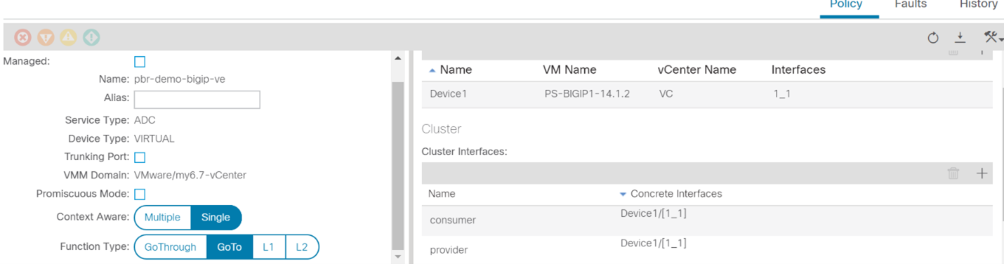
3) Logical Device Cluster- Under Tenant->Services->L4-L7, create a logical device
- Managed – unchecked
- Name: ‘pbr-demo-bigip-ve`
- Service Type: ADC
- Device Type: Virtual (in this example)
- VMM domain (choose the appropriate VMM domain)
- Devices: Add the F5 BIG-IP VM from the dropdown and assign it an interface
- Name: ‘1_1’, VNIC: ‘Network Adaptor 2’
- Cluster interfaces
- Name: consumer, Concrete interface Device1/[1_1]
- Name: provider, Concrete interface: Device1/[1_1]
4) Service graph template
- Under Tenant->Services->L4-L7->Service graph templates, create a service graph template
- Give the graph a name:’ pbr-demo-sgt’ and then drag and drop the logical device cluster (pbr-demo-bigip-ve) to create the service graph
- ADC: one-arm
- Route redirect: true

5) Click on the service graph created and then go to the Policy tab, make sure the Connections for the connectors C1 and C2 and set as follows:
- Direct connect – True
- Adjacency type – L3

6) Apply the service graph template
- Right click on the service graph and apply the service graph
- Choose the appropriate consumer End point group (‘App’) provider End point group (‘Web’) and provide a name for the new contract
- For the connector
- BD: ‘F5-BD’
- L3 destination – checked
- Redirect policy – ‘bigip-pbr-policy’
- Cluster interface – ‘provider’
Once the service graph is deployed, it is in applied state and the network path between the consumer, F5 BIG-IP and provider has been successfully setup on the APIC
Configuration on BIG-IP
1) VLAN/Self-IP/Default route
- Default route – 10.168.57.1
- Self-IP – 10.168.57.10
- VLAN – 4094 (untagged) – for a VE the tagging is taken care by vCenter
2) Nodes/Pool/VIP
- VIP – 10.168.57.11
- Source address translation on VIP: None
3) iRule (end of the article) that can be helpful for debugging
Few differences in configuration when the BIG-IP is a Virtual edition and is setup in a High availability pair
2) APIC: Logical device cluster
- Promiscuous mode – enabled
- Add both BIG-IP devices as part of the cluster

3) APIC: L4-L7 Policy-Based Redirect
- L3 destinations: Enter the Floating BIG-IP Self-IP and MAC masquerade
Configuration is complete, let’s look at the traffic flows.
Client-> F5 BIG-IP -> Server

Server-> F5 BIG-IP -> Client
In Step 2 when the traffic is returned from the client, ACI uses the Self-IP and MAC that was defined in the L4-L7 redirect policy to send traffic to the BIG-IP.
iRule to help with debugging on the BIG-IP

Output seen in /var/log/ltm on the BIG-IP, look at the event <SERVER_CONNECTED>
Scenario 1: No SNAT -> Client IP is preserved

If you are curious of the iRule output if SNAT is enabled on the BIG-IP – Enable AutoMap on the virtual server on the BIG-IP
Scenario 2: With SNAT -> Client IP not preserved.

Conclusion:
Use PBR functionality on the Cisco ACI fabric to direct return traffic from the application servers back to the BIG-IP. This will help in having to avoid to re-write your application or to make changes to your BIG-IP configuration and still achieve a symmetry traffic flow with minimal changes.
References:
F5 BIG-IP and Cisco ACI whitepaper
Layer4-Layer7 services deployment guide
Service graph:
Cisco APIC Layer 4 to Layer 7 Services Deployment Guide, Release 4.0(1)
Cisco APIC Layer 4 to Layer 7 Services Deployment Guide, Release 4.0(1) – PDF


Client and server both have same ip ?? Looks like a typo, doesn’t it ?
No, they don’t… Client is 10.168.x.x, server is 192.168.x.x