
Simplicity has become the new mantra within IT, especially within the datacenter. An abstracted intent driven policy model is the foundation to achieving simplicity. Cisco pioneered this concept back in 2009 with the release of UCS, introducing a radical shift in how compute services are delivered. The desired compute need can be described in an abstracted policy model and automatically orchestrated across a unified compute fabric (compute/peripherals/storage/network).
ACI brought a similar intent driven model to the datacenter networking fabric. Users can model their ideal network topology in a very simplistic user interface and that policy is delivered across a very sophisticated VXLAN host-based routed fabric. ACI automates complex tasks like creating VRFs consistently across a fabric, setting up anycast gateways on all leafs, configuring the underlay and overlay routed networks to support a VXLAN topology, extending networking and security policies across physical sites or into the cloud, and much more.
And now the problem 😕
One very common and popular use case for ACI is managing network segments for workloads to consume, especially for hypervisor based workloads. In the past, the process of properly plumbing a network segment all the way down to the virtual switch required coordination across multiple teams. Network operators needed to ensure the VLAN was properly defined upstream, routing was configured for that network, and the VLAN was trunked across all switches where needed. The hypervisor operators would then need to ensure the same VLAN id was configured properly within the virtual switch across all hypervisor hosts where needed. If any of the hypervisor hosts lived in a blade enclosure where vendor specific networking elements were used then the server operating team would also need to ensure the VLAN was configured properly through the blade switching fabric.
With all of these potential touch points, the theoretically simple task of extending a new networking segment to virtual workloads could be very error prone and susceptible to lengthy delivery times…….but there’s a much simpler way…..ACI to the rescue!! With ACI, the delivery of this network segment can be fully delivered to the virtual switch with multi-tenant segmentation included. This takes care of the physical and virtual networks however server enclosure switching would still need to be configured properly by the server operations team. While UCS provides a programmable compute fabric which makes creating these VLAN segments simple and consistent, operationally ACI and UCS were ships in the night completely operated by different teams thus requiring a coordinated effort.
Better Together FTW 💡
With the 4.1.1 and above release of ACI these two ships have joined forces to completely remove the operational overhead!! For the remainder of this post we will look at how VMM integration is configured inside of ACI, how we had to separately configure UCS in the past, and how this new ACI+UCS integration makes the task simpler.
VMM integration with ACI
Integrating ACI with a VMM (virtual machine manager) domain such as vCenter is very easy to do using the ACI UI. Please watch the video below for a detailed walkthrough.
Testing Connectivity: First Attempt
At this point ACI has helped automate the delivery of multiple multi-tenant network segments (EPGs) throughout the physical and virtual networks. Now let’s attach some linux test VMs to these new networks and verify connectivity.
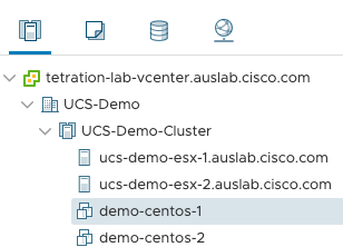
Centos VM 1
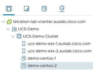
Centos VM 2
From within the vCenter web console for demo-centos-1 we can check if an IP address was properly allocated via DHCP.
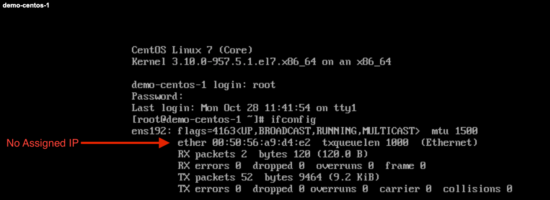
It appears that our test vm did NOT properly receive an IP allocation from the DHCP server. What went wrong?
ACI has handled configuring the network segment through the physical and virtual fabric but what about server networking within the UCS compute fabric? Let’s investigate.
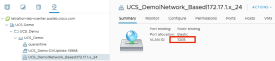
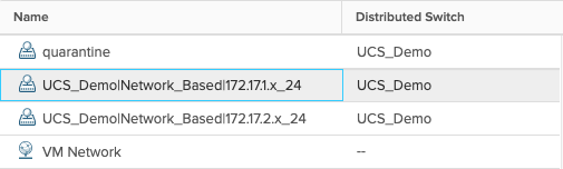
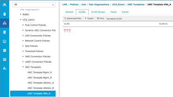
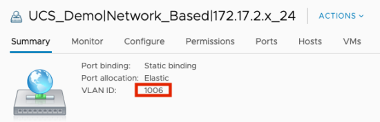
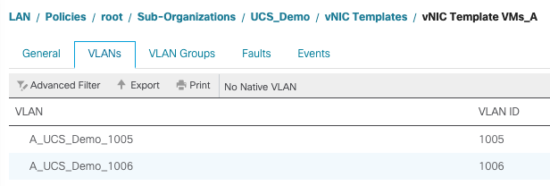
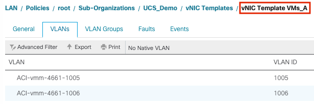
As shown above, one of the dynamic VLAN IDs (1005) was checked out of the pool created in ACI and assigned to the distributed port group our test VM is using. However, inside of UCS Manager the VLAN list for the vNIC template of the ESX host is blank. This would definitely explain why reachability is broken.
Now let’s add VLAN 1005 to the UCSM VLAN definitions as well as to the vNIC template and re-test.

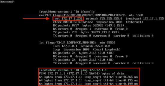
The test vm now successfully negotiates a DHCP address and is able to ping its default gateway. Rinse and repeat this process for the second EPG.
In the past, you could minimize this operational overhead by pre-populating all of the VLANs from the dynamic VLAN pool in ACI into UCSM. The drawback to this approach is you are creating unnecessary overhead (STP logical ports) for network segments that may not be in use.
A Better Approach
With the release of ACI version 4.1.1 and above, a new capability has been added called Cisco ACI with Cisco UCSM integration. Today, this integration is specifically for VMM domains deployed on an FI-based UCS compute fabric. The following pre-requisites are required for this new integration to work:
- Cisco Application Policy Infrastructure Controller (APIC) Release 4.1(1) or later
- Cisco UCS and Cisco UCSM properly installed and configured in your data center
- Cisco UCSM 3.2 or later
- UCSM vNIC templates that are configured as Updating Template type
- Creation of a VMware VMM domain or a Microsoft System Center Virtual Machine Manager (SCVMM) domain (vCenter example is shown in the first part of this blog)
- Installation of the Cisco External Switch app, which can be found in the Cisco ACI App Center on Cisco.com (video demo below)
Below we will go through all of the steps necessary to setup the integration. For further reference, the full integration guide can be found here
Setting up the Integration
1. Ensure you’ve met the pre-requisites listed above
2. Install the External Switch ACI app and configure the UCSM Integration
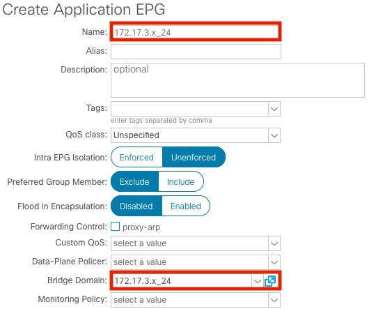
3. Create a new EPG
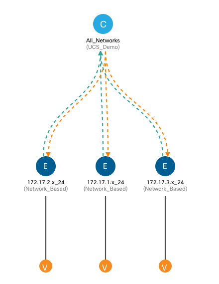
Now that the integration setup is complete let’s create a new EPG and see how things have changed operationally. Back in the ACI user interface we can repeat the procedure from Step 3 in the VMM Integration with ACI section to create a third EPG.
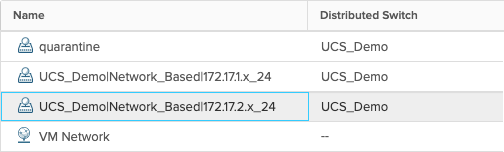
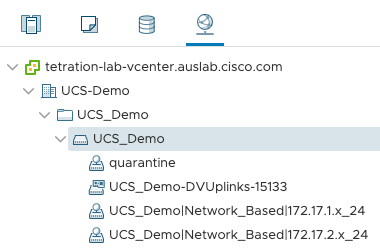
Now we can verify that the new port group was created on the ACI managed VDS.
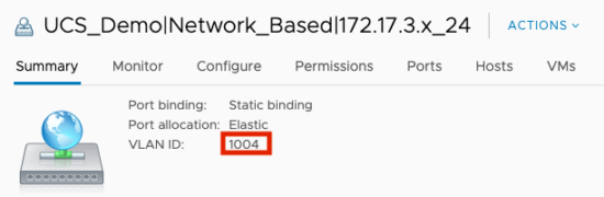
As shown in the screen capture above, ACI assigned VLAN 1004 from the dynamic pool to the newly created port group mapped to our EPG. This is where the wheels fell off previously because the VLAN was not yet defined within the UCS fabric. We can now go back into UCSM to verify.
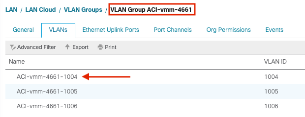
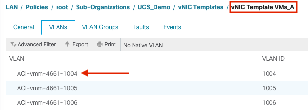
In the screen captures above we can see that VLAN 1004 was correctly added to our VLAN Group managed by the ACI+UCS integration and was also added to our VNIC templates for the ESX hosts. Now we can assign another test VM to this newly created port group and test connectivity.
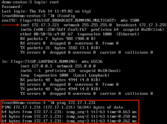
Our test VM was successfully assigned a DHCP address and is able to ping our first test vm in the 172.17.0/24 subnet. Mission accomplished!!!
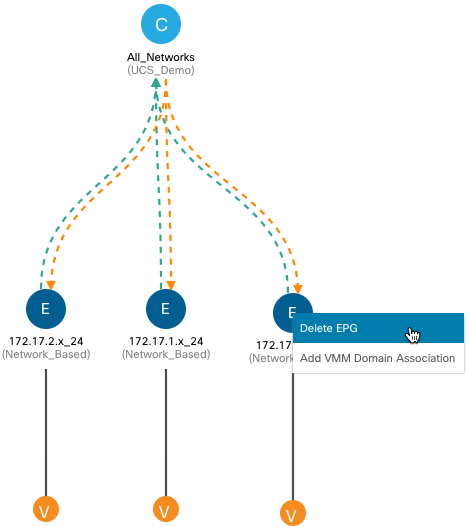
But what about cleanup???
The ACI+UCS integration connects the dots between ACI and UCS for creating new EPGs within our VMM Domain but what about teardown? Simple enough to test, let’s delete the EPG we created in the last section.
Validating in vCenter
Validating in UCSM
From the screen captures above we can see that the port group was properly removed from the VDS in vCenter AND the VLAN was also removed from the VLAN group and VNIC templates in UCSM.
Final Thoughts
If simplicity is the ultimate goal then the ACI+UCS integration helps get you that much closer to the finish line. Together these two solutions provide intent driven policy models that simplify how network and compute services are delivered within your datacenter anywhere environments.


This is not exactly mind boggling work and to be honest I am surprised it even took this long. Still it’s cool that it is finally there.
The UCS FIs are still intermediate switches which would not be necessary if the functionality would be integrated into the leaf switches. But sadly this seems to be too complicated though. So nice workaround but still only a workaround.
Ex-Coal Miners were doing this with Postman five years.