
This is Part I in a four part series of blogs.
Micro-segmentation has become a buzzword in the networking industry. Leaving the term and the marketing aside, it is easy to understand why customers are interested in the benefits that Micro-segmentation provides.
The primary advantage of Micro-segmentation is to reduce the attack surface by minimizing the possibilities for lateral movement in the event of a security breach. With traditional networking technologies this is very hard to accomplish. However, SDN technologies enable a new approach, by allowing degrees of flexibility and automation not possible with traditional network management and operations, making Micro Segmentation a distinct possibility.
I describe ACI Micro Segmentation capabilities in this short presentation I did at Network Field Day during Cisco Live Berlin.
From Theory to Practice
This is the first of a series of blogs where we will illustrate how to leverage Cisco ACI to implement Micro Segmentation through various basic but practical examples. We will look at leveraging the ACI EPG and contract-based policy model combined with micro EPGs (uEPGs) and several other ACI features.
We will be considering a fictitious company – Acme Co. – that is implementing ACI and explores how to use some of the fabric capabilities in order to enhance the security posture inside the perimeter of the DC. Each blog will describe and provide a demo for a specific use case.
In this blog, we look specifically at how application designers can benefit from the ACI white-list policy model and micro segmentation in order to keep multiple application tiers in a single subnet. We will also see how ACI can be used to automate insertion of L4-7 devices that provide services for these applications. In the demo, we will also introduce the ACI vCenter Plugin in order to illustrate how vSphere administrators can configure ACI Micro Segmentation from a tool that is familiar to them.
In the next blog we will imagine that Acme Co. wants to change that application and will create a development and testing environment. We will see how they can share the same infrastructure for dev/test, and how the administrator can dynamically create a development and testing environment to modify the application described later in this blog. We will see how easy it is to do this in ACI, and show how administrators can change Virtual Machines from one stage to another by simply modifying VM attributes without requiring any fabric or VM network reconfiguration.
In the third blog we will shift gears to look at using Micro Segmentation to secure the infrastructure on which the applications from the previous examples is running. Acme Co. infrastructure administrators will use ACI to enhance security for the physical server provisioning and the vSphere infrastructure itself. While we will be using vSphere infrastructure on Cisco UCS for these examples, the principles and configurations are applicable to other virtualization and server environments as well.
Finally, in the fourth blog of the series we consider Day-2 operations and look how Acme Co. operators can leverage APIC tools to simplify troubleshooting and do root-cause analysis of failure scenarios including link or node failures, configurations human mistakes, etc.
We hope that through these posts we will help customers and partners get a better idea of how ACI can help them in their organizations. Feedback is welcomed as to whether we achieve that objective or not! 🙂
Now, on to our first example: Acme Co. implements a new online web shop.
In this example we look at how applications can benefit from the ACI policy model and micro segmentation to keep multiple application tiers running in a single subnet with lateral movement protection implemented through a white-list model for a Zero Trust approach. We will illustrate this with a very basic example with just two-tiers, but the model can expand to any number of tiers.
Let’s imagine that Acme Co. is building an online web shop. We will do this with a simple default installation of the open source Joomla Content Management System (CMS) and use one of the sample sites. Joomla is a CMS similar to WordPress, relying on an Apache web server and a SQL database. The apache server has static web content, and the DB maintains dynamic web content. To simplify IP Address Management (IPAM) in order to facilitate automation, the intention is that all servers will share the same subnet.
The application will be available to external users, and we will protect it by having a perimeter Next Generation Firewall (NGFW) as it is commonly done in Enterprise deployments. We will also use a Load Balancer before the apache servers. The following drawing depicts the high level “design” of our [very] basic application, showing the intent of the white-list model allowing only the protocols and ports strictly required.
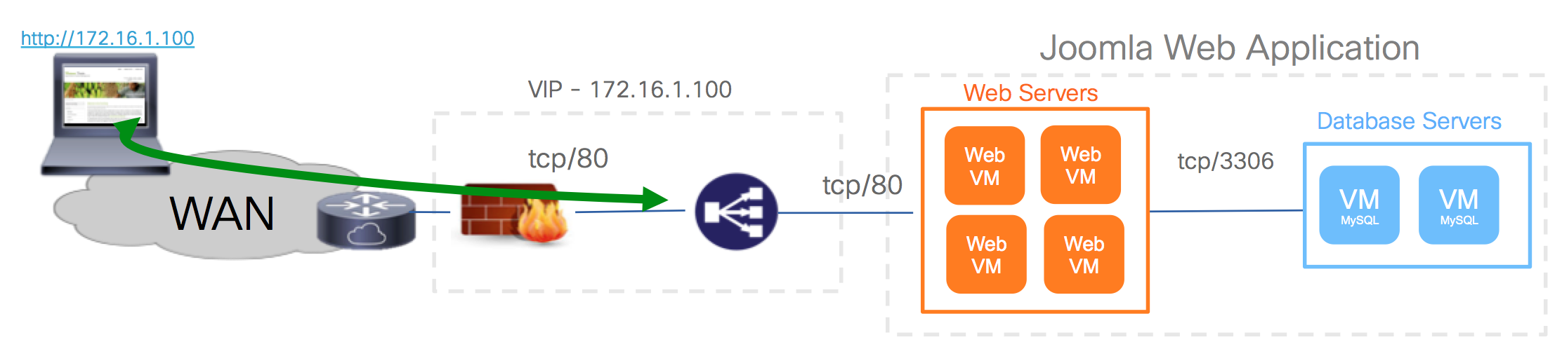
With a traditional network design, we would have used one subnet and VLAN for the database, and another subnet and VLAN for the web servers. Very likely, these two subnets would be connected to different interfaces of a firewall where we would open the right ports between them.
But let’s forget the traditional approach.
For Acme Co. engineers, the desired end goal would be something like this, where green arrows indicate allowed communication, red arrows indicate blocked communications: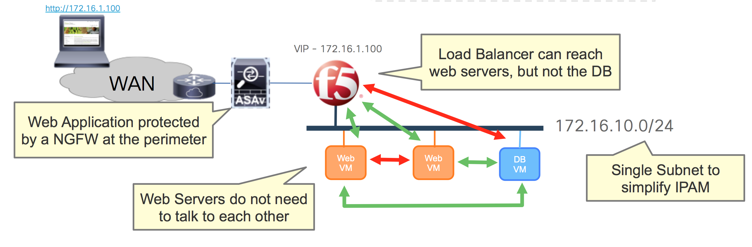
The perimeter NGFW would perform application level inspection and probably NAT towards internal addresses, and the load balancer should be able to off load SSL and provide advanced load balancing features. It is definitely very possible that these devices are physical and shared for other applications as well, although in our demo we will use virtual devices.
The only IP address that needs to be accessible from the outside networks is the VIP programmed on the load balancer for this application. The load balancer should not have access to the database, even if they are on the same segment, but only to the web machines that are part of the load balancing pool. Only the Web servers should have access to the DB, and they do not need to communicate with one another.
We will set this application with all servers as Virtual Machines running CentOS 7 on vSphere 6.0. We will use a Cisco ASA with SourceFire and an F5 load balancer.
Implementation with ACI Policy Model and Micro Segmentation
In this post I am not going to go through any basic ACI setup. I will assume the reader already knows how to build an ACI fabric and is familiar with key concepts like VMM Domains, tenants, VRFs, Bridge Domains, EPGs and contracts.
In this example, I imagine that Acme Co. has created an ACI tenant dedicated to new virtualized applications. In that tenant, we need one VRF and one Bridge Domain. Within that tenant, the fabric administrator or the vSphere administrator (or both) can create an Application Network Profile (ANP) that describes the application from above. The Application Profile will look as follows:
 We will be using one EPG and two micro EPGs (uEPGs), initially all in the same Bridge Domain and subnet and all mapped to a vSphere VMM Domain. The uEPG Web-Prod will host the Apache Web servers and the uEPG DB-Prod will be for the MySQL servers.
Then we have ‘JoomlaAppServers’ EPG. This will be what we call our base EPG. This means that this EPG will generate the configuration of a matching dvPortGroup on the vSphere Distributed Switch of the VMM domain. This can be the native vSphere Distributed Switch (VDS) or the Cisco Application Virtual Switch (AVS).
We will connect all the Virtual Machines for our Joomla-based application on that dvPortGroup. This means all apache and MySQL servers are on the same dvPortGroup. From this base EPG JoomlaAppServers the Virtual Machines only have access to the provisioning tools. So we just launch CentOS VMs from a template image, connect them to the JoomlaAppServers dvPortGroup and let Ansible provision MySQL, Apache, Joomla, etc.
Do we need this extra EPG? … Not necessarily. Just like you don’t really *need* to use uEPGs here. We could have had two normal EPG for Web and DB, or a base EPG for Web and a uEPG for DB … But we are using this base EPG as a staging environment and we will see it’s useful in following demos/blogs.
Once a VM has been provisioned for a certain function, we need to change the applied policy to implement our application. This will mean changing the VM to its right uEPG. The uEPGs allow dynamic classification of VMs into different policy environments. To change the VMs into the right uEPG, we configure them with the correct VM attributes so there is no need to change them from one dvPortGroup to another. With vSphere, the idea is to use Custom Attributes to describe the environment and policy that a VM requires. However for the demo you will see below we use the VM name instead, simply because it is easier to edit it directly from the vCenter GUI for demo purposes.
Once the VM Attributes identify a VM to be part of one uEPG or another, the VM vNIC will remain in the same dvPortGroup, but the VM vNIC as an endpoint now will belong to the uEPG, and have the corresponding policy applied.
In our example, the VMs in the Web-Prod uEPG can only access the VMs in DB-Prod uEPG and only using TCP/3306. The Web-Prod uEPG is isolated, so the VMs in this group can’t communicate to one another. The VMs in the DB-Prod uEPG can’t access anything at all: they can only reply to connections from Web-Prod EPG for TCP/3306.
What about External Connectivity?
North-South connectivity is fundamental for the performance of any web-based application. It is useless to have a high performance backend if the end-user experience is limited by long delays accessing the web front end.
In ACI, north-south connectivity is accomplished by connecting physical ports of ACI switches to the DC Routers. These ports are configured as L3Out interfaces and can be shared by many applications and tenants, or can be dedicated as well. These ports can be 10GE or 40GE and should be configured with redundancy of course. The L3Out interface will have associated “external EPGs” to abstract the representation of external endpoints.
In our case, we’ve created an external EPG that represents a “default” route to represent all hosts external to our application. A contract between that external EPG (AcmeWAN) and the Web-Prod EPG will enable users to access our application.
This contract allows any external host to access the VMs in Web-Prod uEPG on port TCP/80 by having the traffic flow before through a NGFW and a LB. These devices are inserted in the path through a Serv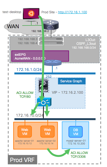 ice Graph. In our demo we use a managed Service Graph, which means that we are also configuring NAT, NGFW rules, LB VIP, etc through the APIC.
Specifically, we are configuring a VIP on an F5 load balancer and a dynamic pool of servers that wi
ll contain all the VMs that are in Web-Prod uEPG. We are configuring the NGFW to allow only access to the VIP and to inspect TCP/80 traffic.
It is important to notice that if an external host would attack/scan the VIP, all non-TCP/80 traffic will be dropped (and logged) in hardware by the fabric, therefore not wasting any resources on the NGFW.
Next to these lines you can see a detailed logical design of the final environment we will show in the demo.
As an important clarification: in my lab I happened to have easy access to ASA as an NGFW and F5 BIG-IP as an ADC. Similarly, I built this using vSphere 6.0 with all servers virtualized in this case. But this demo can be built using other vendors for L4-7 and other hypervisors as well.
In future blogs I will demo how the same ACI Application Profile can be used if the application from the diagram above is deployed on Microsoft Hyper-V, OpenStack, Docker containers and/or combinations of those and bare metal. No additional licenses are required for ACI to work with one virtualization environment or another, or all of them at once. Clearly, more sophisticated application designs can be accomplished with the same principles discussed here as well.
And finally, here’s the demo … if you read the blog, you can probably fast forward to minute 3:10, where the real demo begins 🙂
Thanks to Minako Higuchi (@mihiguch) for helping with the demo and early blog reviews 🙂


Superb! Well done Juan 🙂
Great demo Juan – extremely informative!
Nicely done!
I have a lab setup with VMWare 5.5 and ACI 1.2(3c). I’ve noticed your vSphere Web client has lot more “ACI tools” in the navigation pane. I’m not seeing the same tools in my setup.
Do I need to add “ACI Tools” into the VMWare vSphere application or do I need to upgrade VMWare and\or ACI?
thanks for the kind words 🙂
@Glen,
the “ACI Tools” you may be referring to on vCenter are thanks to the ACI vCenter Plugin. This is an optional plugin that I am using as a “preview” in my demos. It will be available on CCO with the ACI 2.0 release in a few weeks, and it will work with vCenter 5.5 as well as 6.0.
I hope this helps!
Juan to be clear for you to get VM-attributes you need AVS installed. Just Vmware VDS will not let you group VM’s into uSeg EPG’s?
Ok just to be very clear: for you to get VM-attributes to group VM into uEPG, you do NOT need AVS. This works also with the VDS since APIC 1.3(1g) with EX model switches as leafs. It is very clear on the release notes: http://www.cisco.com/c/en/us/td/docs/switches/datacenter/aci/apic/sw/1-x/release/notes/apic_rn_131.html#_Toc423506698
Similarly, the vCenter Plugin that I show on the demo works on both AVS and VDS VMM Domains, however this requires APIC 2.0 that will be shipping soon. Hope this clarifies.
got it thanks.
This was a really helpful blog entry, thank you!
Regarding the micro-segmentation support using the EX series and DVS rather than AVS, where does the policy get enforced in that case? Is it being enforced by the DVS, or does the traffic come up to the leaf?
Great job Juan. Great example, well put together and informative. I enjoyed reading and watching.
Thanks once again for the kind comments.
@Matt, if you use micro EPGs with DVS having EX series, we program the dvPortGroup to only allow traffic sent to the leaf. At the leaf we classify per vNIC into the right uEPG. So yes, the policy is enforced at the leaf indeed, not the VDS. If you have levels of affinity this is sub-optimal, but even then the actual impact on application performance is usually marginal, and the advantage is that you do not have to install any additional bits on the hypervisor, thus keeping it simpler for all purposes. That said, AVS gives extra advantages so I tend to recommend it.
Hi Juan, thanks for the explanation. Regarding EX leaf switches support for Vmware DVS, what actually gets configured in leaf policy so that traffic always goes to the leaf even when its the same VM port group. When two VMs in the same ESXi on the same port group try to communicate, in a usual scenario, they will be switched through the DVS itself and never go to the leaf. What is so special with ACI managed vmware DVS? Why can’t E-series leafs support this?
Hi Juan, in addition to me question above, I am looking at it from microsegmentation perspective.
Hello Sakshi, thanks for reading and thanks for the question. We don’t need any magic at the VDS dvPortgroup level. When you configure a regular EPG and map it to the VDS-based VMM domain you can now click on “allow micro segmentation”. When we do this, we program the dvPortGroup as an isolated PVLAN. This disables VM to to VM communication locally, and all traffic has to flow through the leaf. At the leaf there are various ways we can identify each endpoint of course, so that when you configure a uEPG, we can place the endpoint’s MAC traffic under the right uEPG and apply the right policy. A VM in the base EPG and/or on a uEPG may still need to talk to another VM on the same EPG/uEPG on the same hosts, so that means we need to proxy-arp as well. All of this together requires working with EX-based hardware. There are no hardware requirements though if you use the AVS. In the case of the AVS the implementation is clearly very different. I hope this clarifies! 🙂
Juan, I have seen a number of ACI demos since it’s inception over two years ago, and this series of demos (all three), are by far, the most powerful, useful and informative demos I’ve seen. Simply awesome. The videos are especially just amazing. Keep it up! 🙂
VERY HELPFUL. THANK YOU.