Switches are the heart of a network data plane and at the heart of any switch is the buffering subsystem. Buffering is required to deal with transient oversubscription in the network. The size of the buffer determines how large of a burst can be accommodated before packets are dropped. The goodput of the network depends heavily on how many packets are dropped.
The amount of buffer needed for optimal performance is mainly dependent on the traffic pattern and network Round-Trip Time (RTT).
The applications running on the network drive the traffic pattern, and therefore what the switch experiences. Modern applications such as distributed storage systems, search, AI training, and many others employ partition and aggregate semantics, resulting in traffic patterns that are especially effective in creating large oversubscription bursts. For example, consider a search query where a server receives a packet to initiate a search request. The task of mining through the data is dispatched to many different servers in the network. Once each server finishes the search it sends the results back to the initiator, causing a large burst of traffic targeting a single server. This phenomenon is referred to as incast.
Round-Trip Time
The network RTT is the time it takes a packet to travel from a traffic source to a destination and back. This is important because it directly translates to the amount of data a transmitter must be allowed to send into the network before receiving acknowledgment for data it sent. The acknowledgments are necessary for congestion avoidance algorithms to work and in the case of Transmission Control Protocol (TCP), to guarantee packet delivery.
For example, a host attached to a network with a 100Gbps link through a network with an RTT of 16us must be allowed to send at least 1.6Mb (16us * 100Gbps) of data before receiving an acknowledgment if it wants to be able to transmit at 100Gbps. In TCP protocol this is referred to as the congestion window size, which for a flow is ideally equal to the bandwidth delay product.
The amount of buffer a switch needs to avoid packet drop is directly related to this bandwidth delay product. Ideally a queue within a switch should have enough buffer to accommodate the sum of the congestion windows of all the flows passing through it. This guarantees that a sudden incast will not cause the buffer to overflow. For Internet routers this dynamic has been translated to a widely used rule of thumb – each port needs a buffer of average RTT times the port rate. However, the datacenter presents a different environment than the Internet. Whereas an Internet router can expect to see 10s of thousands of flows across a port with the majority bandwidth distributed across 1000s of flows, a datacenter switch often sees most of the bandwidth distributed over a few high bandwidth elephant flows. Thus, for a datacenter switch, the rule is that a port needs at most the entire switch bandwidth (not just the port bandwidth) times average RTT. In practice of course this can be relaxed by noting that this assumes an extremely pessimistic scenario where all traffic happens to target one port. Regardless, a key observation is that the total switch buffer is also the entire switch bandwidth times average RTT, just like for the Internet router case. Therefore, the most efficient switch design is one where all the buffer in the switch can be dynamically available to any port.
 Figure 1. Buffer requirement based on RTT
To help understand the round-trip times associated with a network, let’s look at a simple example. The RTT is a function of the network physical span, the delay of intermediate switches, and end nodes delay (that is the network adapters and the software stack). Light travels through fiber at about 5us per kilometer, so the contribution of the physical span is easy to calculate. For example, communication between two hosts in a datacenter with a total fiber span of 500 meters per direction will contribute 5us to the RTT. The delay through switches is composed of pipeline (minimum) delay and buffering delay.
Low delay switches can provide below 1us of pipeline delay. However, this is an ideal number based on a single packet flowing through the device. In practice, switches have more packets flowing through them simultaneously, and with many flows from different sources some minimum buffering in the switches is needed. Even a small buffer of 10KB will add almost 1us to the delay through a 100Gbps link.
Finally, optimized network adapters will add a minimum of two microseconds of latency, and often this is much more. So, putting this all together we can see that even a small datacenter network with 500 meters of cable span and three switching hops will result in a minimum RTT of around 16us. In practice, networks are typically never this ideal, having more hops and covering greater distances, with even greater RTTs.
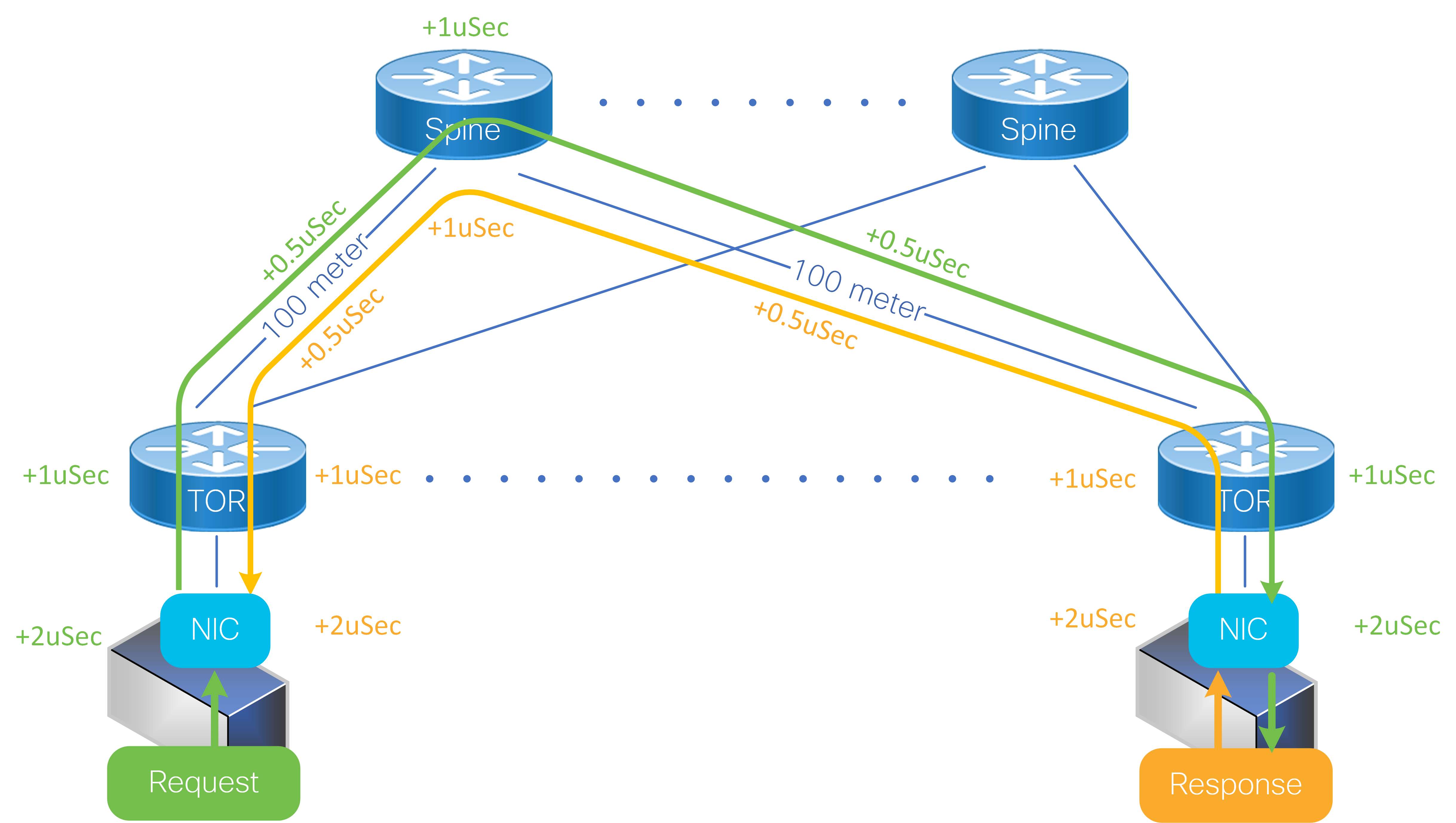 Figure 2. Simple Datacenter Network – minimum RTT
As can be seen from the figure above, supporting a modest RTT of 32us in a 25.6T switch requires up to 100MB. It’s important to notice at this point that this is both the total required buffer in the switch and the maximum required buffer for any one port. The worst-case oversubscription to any one port is when all incoming traffic happens to target one port. In this pathological incast case, all the buffer in the device is needed by the victim port to absorb the burst. Other oversubscribing traffic patterns involving multiple victim ports will require that the buffer be distributed in proportion to the oversubscription factor among the victim ports.
It’s also important to note that other protocols, like User Datagram Protocol (UDP) that are utilized by Remote Direct Memory Access (RDMA), don’t have the congestion feedback schemes used in TCP, and they rely on flow control to prevent packet loss during bursts. In this case the buffer is critical as it reduces the likelihood of triggering flow control, thus reducing the likelihood of blocking and optimizing overall network throughput.
Traditional Buffering Architectures
Unfortunately, since the buffer must handle extremely high bandwidth it needs to be integrated on the core silicon die, meaning off-chip buffering that can keep up with the total IO bandwidth is no longer possible as we discussed in our white paper, “Converged Web Scale Switching And Routing Becomes A Reality: Cisco Silicon One and HBM Memory Change the Paradigm”. On-die buffering in high bandwidth switches consumes a significant amount of die area and therefore it’s important to use whatever buffer can be integrated on-die in the most efficient way.
 Figure 3: Bandwidth growth in DDR memories and Ethernet switches
Oversubscription is an unpredictable transient condition that impacts different ports at different times. An efficient buffer architecture takes advantage of this by allowing the buffer to be dynamically shared between ports.
Most modern architectures support packet buffer sharing. However, not all claims of shared memory are equal, and not surprisingly this fact is usually not highlighted by the vendors. Often there are restrictions on how the buffer can be shared. Buffer sharing can be categorized according to the level and orientation of sharing, as depicted in the figures below:
 Figure 4. Shared buffer per output port group
A group of output ports shares a buffer pool. Each buffer pool absorbs traffic destined to a subset of the output ports.
 Figure 5. Shared buffer per input port group
A group of input ports share a buffer pool. Each buffer pool absorbs traffic from a subset of the input ports.
 Figure 6. Shared buffer per input-output port group
A group of input and output ports share a buffer pool. Each buffer pool absorbs traffic from a subset of input ports for a subset of output ports.
In all the cases where there are restrictions on the sharing, the amount of buffer available for burst absorption to a port is unpredictable since it depends on the traffic pattern.
With output buffer sharing, burst absorption to any port is restricted to the individual pool size. For example, an output buffer architecture with four pools means that any output port can consume at most 25 percent of the total memory. This restriction can be even more painful under more complex traffic patterns, as depicted in the figure below, where an output port is restricted to 1/16th of the total buffer. Such restriction makes buffering behavior under incast unpredictable.
 Figure 7. Output buffered switch with 4 x 2:1 oversubscription traffic
With input buffer sharing, burst absorption depends on the traffic pattern. For example, in a 4:1 oversubscription traffic pattern with the buffer partitioned to four pools, the burst absorption capacity is anywhere between 25-100 percent of total memory.
 Figure 8. Input buffer utilization with 4:1 oversubscription traffic
Input-output port group sharing, like input buffer sharing, by design, limits an output port to a fraction of the total memory. In the example of four pools, any one port is limited by design to half the total device buffer. This architecture further limits buffer usage depending on traffic patterns, as in the example below where an output port can use only 12.5 percent of the device buffer instead of 50 percent.
 Figure 9: input-output port group buffer architecture with 2 x 2:1 oversubscription traffic
Cisco Silicon One employs a fully shared buffer architecture as depicted in the figure below:
 Figure 10. Cisco Silicon One Fully Shared Buffer
In a fully shared buffer architecture, all the packet buffer in the device is available for dynamic allocation to any ports, so this means sharing the buffer among ALL the input-output ports without any restrictions. This maximizes the efficiency of the available memory and makes burst absorption capacity predictable as it’s independent of the traffic pattern. In the examples presented above, the fully shared architecture yields an effective buffer size that is at least four times the alternatives. This means that, for example, a 25.6T switch that requires up to 100MB of total buffer per device and per port needs exactly 100MB on-die buffer if it implements as a fully shared buffer. To achieve the same performance guarantee, a partially shared buffer design that breaks the buffer into four pool will need four times the memory.
The efficiency gains of a fully shared buffer also extend to RDMA protocol traffic. RDMA uses UDP which doesn’t rely on acknowledgments. Thus, RTT is not directly a driver of the buffer requirement. However, RDMA relies on Priority-based Flow Control (PFC) to prevent packet loss in the network. A big drawback of flow control is the fact that it’s blocking and can cause congestion to spread by stopping unrelated ports. A fully shared buffer helps to minimize the need to trigger flow control by virtue of supporting more buffering when and where it’s needed. Or in other words, it raises the bar of how much congestion needs to happen before flow control is triggered.
We encourage you to learn more about Cisco Silicon One and its innovative architecture.


Great write up!
Excellent Article and very concise explanation.
Powerful and easy to understand article!
Very informative with nice explanation.
Very clear and concise.
Simplicity at its best – Well articulated & Great Innovation!