It almost feels like this blog entry should start with: Once upon a time…. Because it captures a journey of a young emerging technology and the powerful infrastructure tool it has become. The Cisco UCS journey starts with the tale of Unified Fabric and the Converged Network Adapter (CNA).
Most people think of Unified Fabric as the ability to put both Fiber Channel and Ethernet on the same wire between the server and the Fabric Interconnect or upstream FCoE switchs. That is part of the story, but that part is as simple as putting a Fiber Channel frame inside of an Ethernet frame. What is the magic that makes this happen at the server level? Doesn’t FCoE imply that the Operating System itself would have to know how to present a Fiber Channel device in software and then encapsulate and send the frame across the Ethernet port? Possibly, but that would require OS FCoE software support which would also require CPU overhead and require end users to qualify these new software drivers and compare the performance of software against existing hardware FC HBAs.
For UCS the key to the success of converged infrastructure was due greatly to the very first Converged Network Adapters that were released. These adapters presented existing PCIe Fiber Channel and Ethernet endpoints to the operating system. This required no new drivers or new qualification from the perspective of the operating system and users. However at the heart of this adapter was a Cisco ASIC that provided two key functions:
1.) Present the physical functions for existing PCIe devices to the operating system without the penalty of PCIe switching.
2.) Encapsulate Fiber Channel frames into an Ethernet frame as they are sent to the northbound switch.

It is the second function that we often focus on because that’s the cool networking portion that many of us at Cisco like to talk about. But how exactly do we convince the operating system that it is communicating with an Intel Dual port Ethernet NIC and a Dual port 4GB Qlogic Fiber Channel HBA? I mean these are the exact same drivers that we use for the actual Intel and Qlogic card, there’s got to be some magic there right?
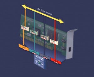
Well, yes and no. Lets start with the no. Presenting different physical functions (PCIe endpoints) on a physical PCIe card is nothing new. It’s as simple as putting a PCIe switch between the bus and the endpoints. But like all switching technologies a PCIe switch incurs latency and it cannot encapsulate a FC frame into an Ethernet frame. So that’s where the magic comes into play. The original Converged Network Adapater contained a Cisco ASIC that sits on the PCIe bus between the Intel and Qlogic physical functions. From the operating system perspective the ASIC “looks” like a PCIe switch providing direct access to the the Ethernet and Fiber Channel endpoints, but in reality it has the ability to move I/O in and out of the physical functions without incurring the latency of a switch. The ASIC also provides a mechanism for encapsulating the FC Frames into a specific Ethernet frame type to provide FCoE connectivity upstream.
The pure beauty of this ASIC is that we have evolved it from the CNA to the Virtual Interface Card (VIC). These traditional CNAs have a limited number of Ethernet and FC ports available to they system (2 each) based on the chipsets installed on the card. The Cisco VIC provides a variety of vNICs and vHBAs to be created on the card. The VIC not only virtualizes the PCIe switch, it virtualizes the I/O endpoint.
So in essence what we have created with the Cisco ASIC, that drives the VIC, is a device that can provide a standard PCIe mechanism to present an end device directly to the operating system. This ASIC also provides a hardware mechanism designed to receive native I/O from the operating system and encapsulate and translate where necessary without the need for OS stack dependencies, for example native Fiber Channel encapsulated into Ethernet.
At the heart of the UCS M-Series servers is the System Link Technology. It is this specific component that provides access to the shared I/O resources in the chassis to the compute nodes. System Link Technology is the 3rd Generation technology behind the VIC and the 4th Generation technology for Unified Fabric within the construct of Unified Computing. The key function of the System Link Technology is the creation of a new PCIe physical function called the SCSI NIC (sNIC) that presents a virtual storage controller to the operating system and maps drive resources to a specific service profile within Cisco UCS.

It is this innovative technology that provides a mechanism for each compute node within UCS M-Series to have it’s own specific virtual drive carved out of the available physical drives within the chassis. This is accomplished using standard PCIe and not MR-IOV. Therefore it does not require any special knowledge of a change in the PCIe frame format by the operating system.
For a more detailed look at System Link Technology in the M-Series check out the following white paper.
The important thing to remember is that hardware infrastructure is only part of the overall architectural design for UCS M-Series. The other component that is key to UCS is the ability to manage the virtual instantiations of the system components. In the next segment on UCS M-Series Mahesh will discuss how UCS Manager rounds out the architectural design.


CONNECT WITH US